Photovoltaic Protection
The need to protect
Photovoltaic (PV) arrays and their associated equipment are expensive assets to purchase and so the need to protect them from the effects of lightning is of paramount importance.
Kingsmill have a range of Earthing, Structural Lightning Protection and Surge Protection products that can be used to provide protection against both the direct and indirect effects of lightning. Products relating to Earthing and Structural Lightning Protection are dealt with in their respective sections.

Application of Surge Protection Devices
A solar photovoltaic system (solar power) is made up of a number of key elements:
- photovoltaic array (solar panel)
- battery charger
- bank of batteries
- inverter to convert DC voltage to AC voltage.
Panels may be protected by a structural lightning protection system, the metallic supports of the arrays should be connected to earth and the heart of the system, the inverter, requires to be protected by Surge Protection Devices.
The inverter should be protected on both the DC side and the AC side, additionally, if the PV arrays are over 10m away from the inverter, an SPD must be installed at the junction box that is local to that PV array.
Basic Principle
The core (key device) of the whole photovoltaic system is the inverter, therefore lightning and transient overvoltage protection should be focused here and it should be incorporated into the whole Lightning Protection System. Additionally, photovoltaic units and their support structures should be integrated into the earthing design.
SPD selection for DC side:
UCPV maximum continuous operating voltage
UOC STC standardised test circuit voltage of the string of PV arrays
UCPV ≥ 1.2 x UOC STC
Where the PV arrays are separated from the lightning protection system, by the “separation distance” calculated in BS:EN 62305-3 and this distance is maintained, OR in the case of no external structural protection, then fit a Type 2 PV surge arrester.
- If the distance between the PV arrays and the inverter is over 10m, a PV SPD has to be fitted to both ends of the DC cable (PV array junction box and DC inverter side).
Where the distance between the PV arrays and the external lightning protection system is not maintained, then fit a combined Type 1 and 2 PV lightning current and surge arrester.
- Always install a PV SPD at both ends of the DC cable (PV array junction box and DC inverter side).
The DC side of the PV system can be either unearthed (insulated) in which case A (top right) shows how SPD’s should be connected OR with one pole earthed, B (bottom right) shows how SPD’s should be connected.
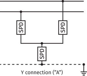
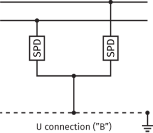
Difference between Y and U connections
All Kingsmill surge protection products for photovoltaic systems are tested in accordance with EN 50539-11.
The main distribution board (AC mains) would have a combined Type 1 & 2 protecter fitted. In addition, any communication lines also require protection.
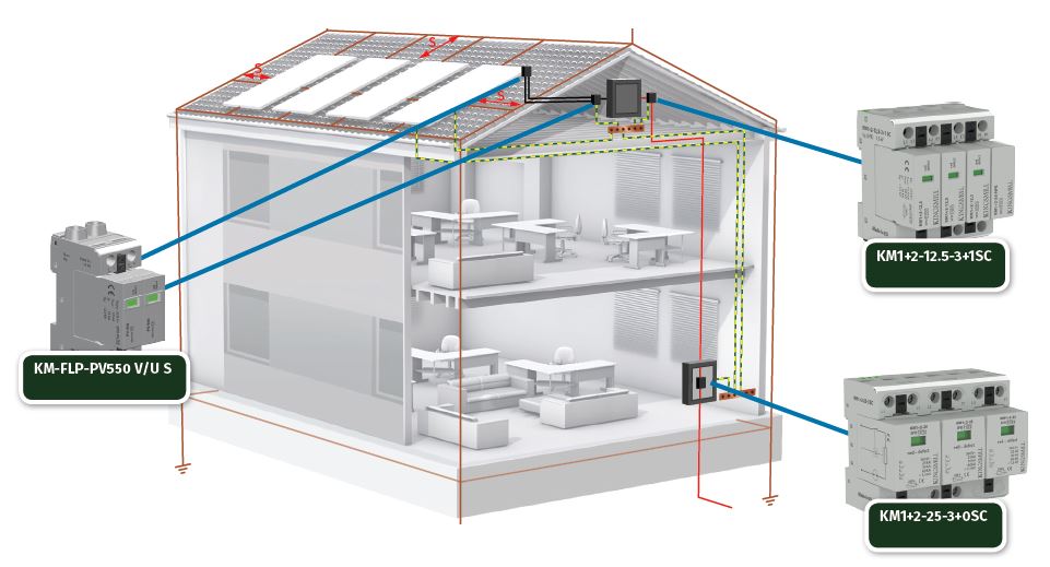
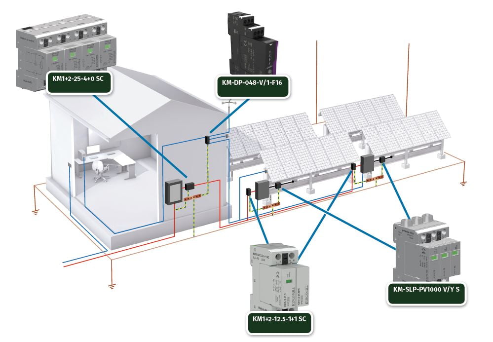
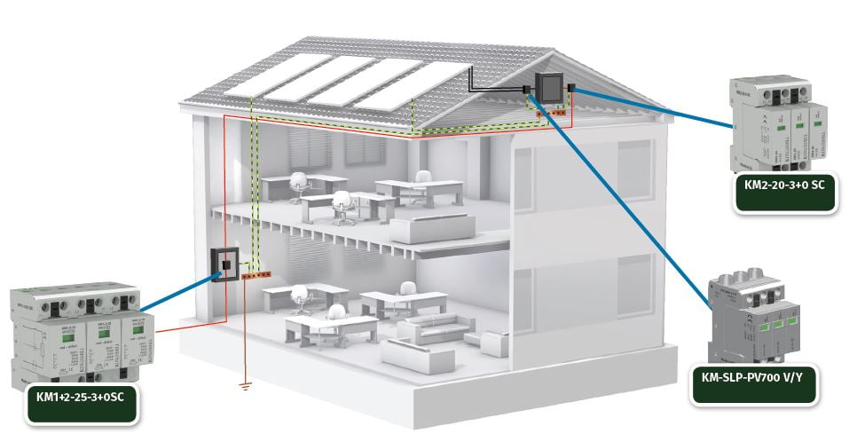
Examples of SPD locations are provided in the following diagrams (units will vary according to site conditions).
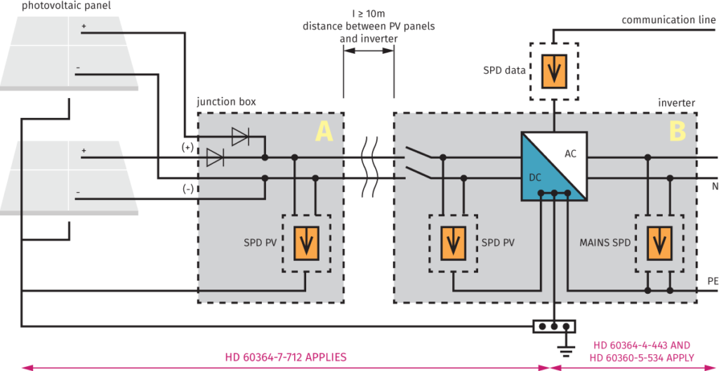
Example – photovoltaic array with a decentralised inverter
*Actual units will vary according to earth system, voltage etc.
Example – roof mounted solar panels (without external LPS or where the separation distance “s” between PV panels and external LPS is maintained)
*Actual units will vary according to earth system, voltage etc.
Example – roof mounted solar panels (where the separation distance “s” between PV panels and external LPS is not maintained)
Separation distance “s” = distance between two conductive parts at which no dangerous sparking can occur
*Actual units will vary according to earth system, voltage etc.
