Conductor Guide
Introduction
- Air Termination Network – arresting the lightning strike
- Down Conductor System – taking the lightning discharge to ground
- Earth Termination/Network – safely dissipating the lightning discharge into the ground.
- Correctly sized for fault current
- Sufficiently robust to resist mechanical damage
- Able to resist the effects of corrosion
Guide to Conductor Selection
Conductors are the most important part of a Lightning Protection and Earthing system.
They:
- Intercept the lightning current
- Carry and safely dissipate the lightning current/earth fault to earth
It is important, therefore, that they:
- Are corrosion resistant
- Carry the current required
- Are mechanically robust
- Provide a low resistivity path to earth
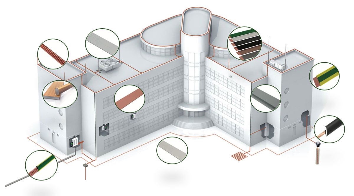
From BS:EN 62305 . . .
Roof Mesh Conductor System
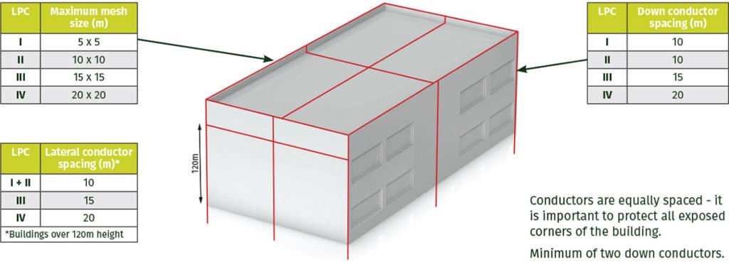
The most common cross-section areas for above ground lightning protection conductors are 8mm dia (50mm2 – BS:EN 62305 min) and 25 x 3mm (75mm2) rectangular section
Selecting the Best Conductor
When choosing the material for the “above ground” Lightning Conductor System, it is important to take into account the avoidance of any bimetallic corrosion. For example, one should avoid the installation of copper conductors over aluminium or steel cladding.
Galvanic corrosion – happens when there is a potential difference between dissimilar metals
When the materials are in contact in the presence of an electrolyte, corrosion occurs. One metal becomes the anode, the other the cathode. The anode will tend to go into solution and therefore corrode. The electrolyte can be water with impurities from the air.
In the instance of water run-off from copper – the water carries fine copper corrosion particles which, when they drip on to aluminium or zinc, may result in corrosion. The direct contact of the dissimilar metals is not required for corrosion to occur in such a case.
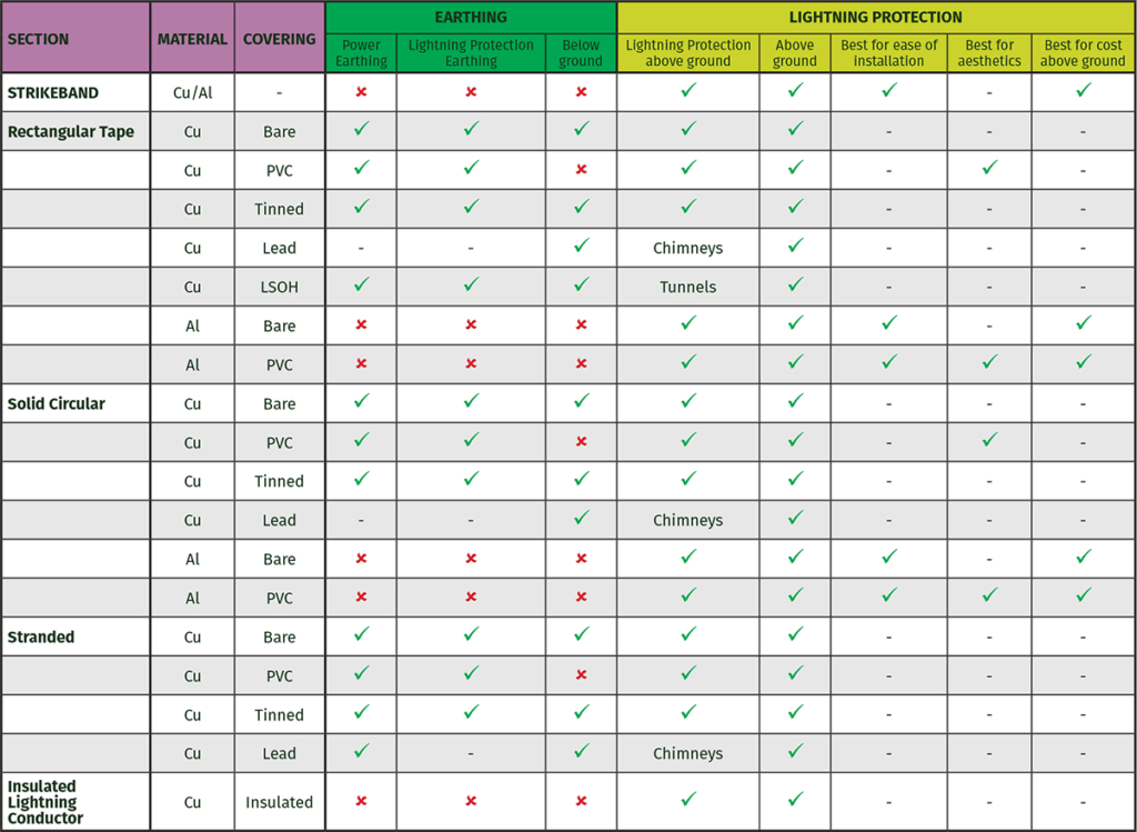
The following table acts as a guide for selecting the best material for use within an earthing and lightning protection system
Whilst there are cautions with respect to the use of aluminium, these can generally be overcome with the use of PVC covered aluminium conductor, in an above ground Lightning Conductor setting.
Lightning Conductor Section Options
STRIKEBAND and aluminium conductors combine the benefits to the installer of light weight and easy installation. Such materials exhibit little “spring back” and so are easier to dress to the contours and shapes of the structure.
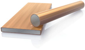
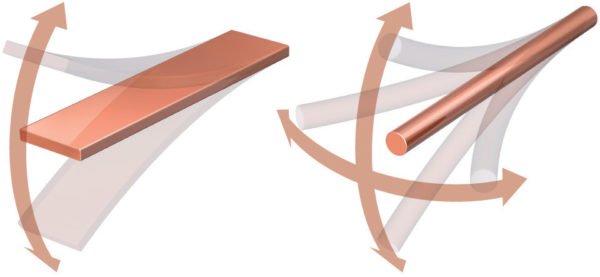
Solid circular section conductors are the easiest to install since they can be bent through any plane (360º) whereas tape can only be bent in two directions.
360º overcomes problems that are presented by complex geometry buildings.
PVC Covered Conductor
Deciding which colour to select is generally governed by the overall aesthetics of the building being protected.
The Kingsmill range of colours is designed to offer the Lightning Protection Designer a range of colours to match commonly used building materials.
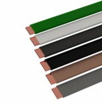
Conductor Colour Chart
PVC covering is often used as a decorative cover when blending in external conductors to building aesthetics. Thought must be given however, to using such conductors in areas of high UV, due to colour bleaching and the life of modern UV stabilisation compounds.

*PVC colours to BS 5252, green to BS 6746C
Conductor Sizing
Earth conductors are sized according to the maximum fault that they are to carry. When carrying out this calculation, it is important to take into account the type of connectors used – exothermic joints will take 100% of the fault current, whereas bolted, braided and crimp connections do not (a chain is only as good as its weakest link).
