Earthing Guide
Introduction
Copper is the recommended material to use in earthing applications, whether below or above ground.
Materials used in earthing systems must be able to:
- withstand mechanical damage
- resist corrosion
- provide a low impedance path to earth
- carry the maximum fault condition for the application/installation
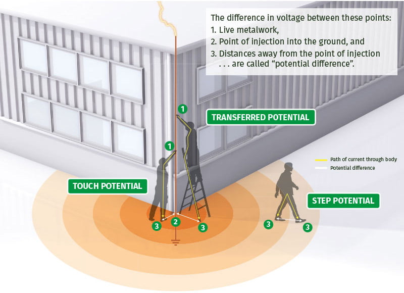
Voltage Gradient
When lightning, or a fault current, is injected into the ground the voltage dissipates through the soil, radiating away from the point of entry. The further the distance from the point of entry, the lower the voltage that will present (much like the size of ripples in a pond, as they radiate away from the point where a stone was thrown into the water).
Mitigation of potential differences can be through the use of “equipotential grids” that equalise potential across an area, plus it is good practice to ensure that the conductors and rods are buried at least 1m deep and covered by a thick layer of insulating material eg rock.
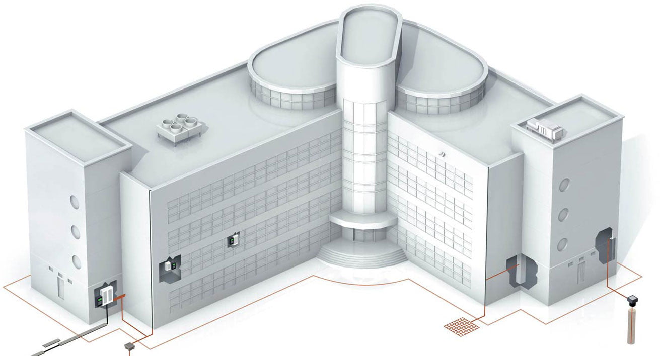
An earth termination network can be installed in different ways . . .
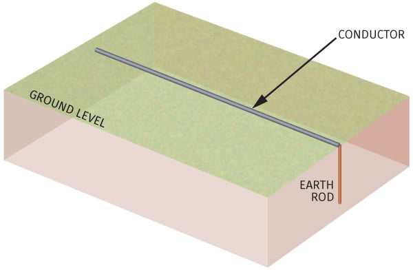
1. Simple Earth Electrode
This can be a driven Earth Rod, an Earth Plate, a Mat or a length of buried conductor – or a combination of both.
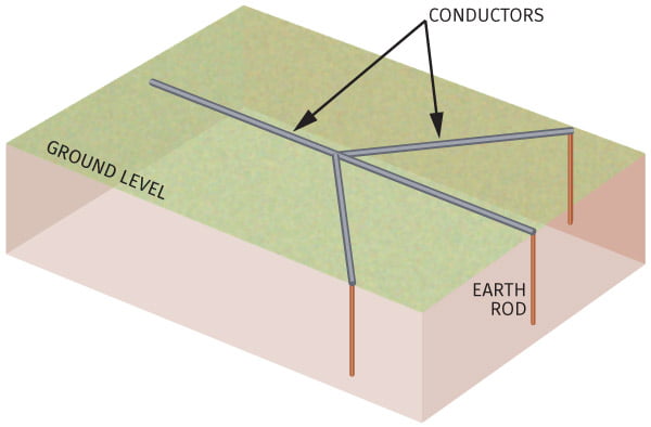
2. Crows Foot Electrode
Can incorporate Earth Rods – the rods would be spaced at least twice their driven length apart.
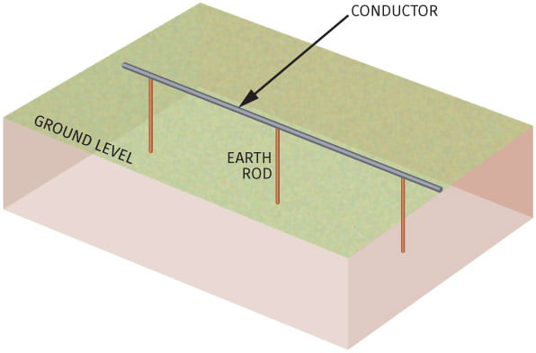
3. Counterpoise Conductor
Can incorporate Earth Rods – the rods would be spaced at least twice their driven length apart.
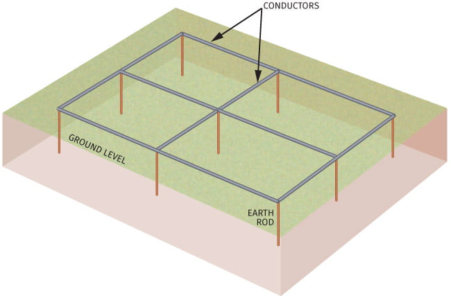
4. Grid Conductor
Can incorporate Earth Rods – the rods would be spaced at least twice their driven length apart. For example, in a sub-station or cell site.
5. Earth Plates/Mats
For example, for protection of an operator at switch positions.
The choice of Earth Termination layout design depends on multiple factors, but essentially . .
- The purpose
- The ground conditions
From BS:EN 62305 . . .
For Lightning Protection, BS:EN 62305:3 advocates two types of Earthing System:
- TYPE A – simple earth electrode
- TYPE B – crows foot or counterpoise. These are ideally suited to areas of high soil resistivity and structures containing electronic equipment and hazardous materials.
- Foundation electrodes may be employed – these are similar to TYPE B and are installed within the building’s foundation itself.
Factors influencing the ability to achieve a satisfactory earth resistivity value
Corrosion resistance is of paramount importance.Soil resistivity readings should be taken prior to designing an Earth Termination Network. The reason for this is that the nature of the soil has a major influence over the final resistivity of the Earth Termination network.This can be illustrated in the following tables . . .
| Moisture Content (% by weight) | ||
|---|---|---|
| 0 | ||
| 2.5 | ||
| 5 | ||
| 10 | ||
| 15 | ||
| 20 | ||
| 30 | ||
Effects of moisture content on resistivity
Effects of temperature on resistivity
Confused? Kingsmill industries is here to help you
Sometimes it is not possible to achieve the desired finished earth electrode resistance, due to the ground conditions being unfavourable – hard rocky ground, mountain tops, dry soil, etc.
For areas where the soil resistivity is very high, Kingsmill offer several “conductive aggregate” solutions to help improve resistivity.
We recommend the use of copper earth electrode systems due to their inherent low resistivity and corrosion resistance.
Our range encompasses:
- Solid copper earth electrodes and conductor
- Solid stainless steel electrodes
- Copperbond (copper covered steel) electrodes and conductor
- Copper conductors
- Earth bars and bonds
- Exothermic welding
Kingsmill do not recommend the use of galvanised, zinc plated or bare mild steel in buried (in direct contact with soil) earth termination networks for two reasons.
- The high resistivity of steel compared to copper
- Poor corrosion resistance when compared with solid copper or copperbonded steel
Similarly, the earth connection components must also be able to resist corrosion and carry the nominated fault rating of the conductor.
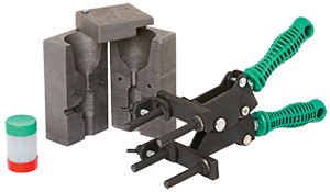
KingsWeld Exothermic Welding
It is important that all Earth Terminations can conduct the current that is required by the Earthing design.
Not only must this apply to the conductor itself, but also to the connectors used within the Earth Termination network. Exothermic joints carry 100% of the conductor fault rating, whereas bolted braided and crimped connections do not. With this in mind, Kingsmill supply a full range of exothermic welding equipment.
Exothermic welds permit the finished joint to carry the full fault rating of the conductors joined, they never loosen and being composed mainly of copper, provide first class corrosion resistance.
The Kingsmill exothermic joint provides:
- Full fault current carrying capacity
- Excellent corrosion resistance
- Ease of installation
However please note, there are instances where a bolted connection is required. For example, where the earth conductor needs to be disconnected from the earth electrode for testing, or where the installation of an exothermic weld is not possible.
A chain is only as good as its weakest link . . . poor component selection can seriously impair a system!