Guide to BS:EN 62305
BS:EN 62305
Lightning Protection design follows the BS:EN 62305 series of documents:
General Principles (Part 1)
HOW TO DESIGN A LIGHTNING PROTECTION SYSTEM
BS:EN 62305-1 introduces key concepts that we used in designing a Lightning Protection System.
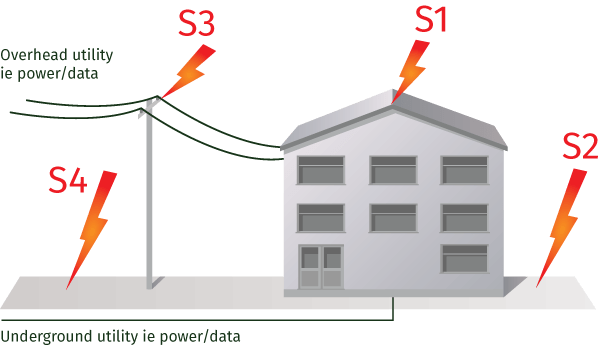
S1 Strike to the structure
S2 Strike to ground near the structure
S3 Strike to overhead utilities connected to the structure
S4 Strike near to utilities connected to the structure
Figure 1: Sources of damage arising from a lightning srike
The types of damage and loss are identified . . .
Types of damage resulting from a lightning strike
D1 Injury to life through step and touch voltages
D2 Physical damage ie fire, explosion etc
D3 Failure/malfunction of electronic systems arising from lightning electromagnetic pulse
Types of loss arising from lightning damage
L1 Loss of human life
L2 Loss of services to the public
L3 Loss of cultural heritage
L4 Loss of economic value ie consequential loss of output and financial impact
A Lightning Protection Level (LPL) is defined . . .
BS:EN 62305-1 defines a Lightning Protection Level (LPL) for the building/structure along with a maximum lightning current associated with that LPL. This LPL is key to the correct application of Lightning Protection. This is considered through Parts 3 and 4 of the standard.
Current division
BS:EN 62305 Part 1 introduces the concept of “current division”. It is assumed that the maximum current due to a lightning strike would be 200kA and that this would flow equally (50%) through the structural lightning protection system (100kA) and 50% through any connected metallic services eg power cables, pipes, etc.
If only one metallic service is connected, eg a power cable, then 100kA would flow through that cable and, in the case of two metallic services, 50kA per service and so on. (The current flowing on a power cable is further divided by the number of cores, as shown in the figure on the right.)
Lightning Protection Zones
Part 1 also introduces the concept of Lightning Protection Zones (LPZ). These are important because they help determine the correct “type” of Surge Protection Device that should be used in a particular zone.
Lightning current SPDs are used at the border of Zones 0 and 1, whereas overvoltage surge arresters are used on the border of Zones 1 and 2, as well as on the border of Zones 2 and 3.
(LPL) | (10/350μs waveform) | Protection System (LPS) | service (50% of current) | – 3 phase (L1, L2, L3, N, E) 4 wires + earth |
|---|---|---|---|---|
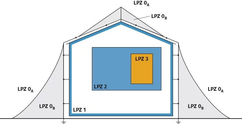
Figure 2: Lightning Protection Levels, as defined by BS:EN 62305-1
Risk Management (Part 2)
BS:EN 62305-2 prescribes how to assess the risk of lightning in respect of loss of life, loss of vital service, economic loss, loss of heritage and physical damage.
This assessment is critical to the correct application of BS:EN 62305-3 and BS:EN 62305-4 and thus the type of product and system to be installed.
The risk management procedure sets out to consider a number of risks associated with the potential losses from lightning induced damage. It combines this with data for ‘local lightning activity’.
Things to note from this assessment:
- Where structural Lightning Protection is required, Type 1 Surge Protection Devices (SPDs) are always
required for metallic electrical services (electricity, data etc). These must form an integral part of any
structural Lightning Protection System. - Where structural Lightning Protection is not required, BUT there is a risk of indirect damage to utility
services entering the structure, Type 1 SPDs are required in the case of overhead connections and Type 2
SPDs for underground cable connections.
Physical Damage to Structures & Life Hazard (Part 3)
In the event of the risk assessment stating that Structural Lightning Protection is required, BS:EN 62305-3 assigns a Lightning Protection Class (LPS) to the LPL and deals, in a prescriptive way, with the application of different design principles to create a structural lightning protection system. The designer has a number of material selection criteria and design concepts available, thus enabling him to overcome protection problems, as well as address corrosion, through the selection of appropriate materials.
The key elements decided being . . .
Air Termination system
Using a mesh system, protective angle, rolling sphere method or combination of these.
Separation distances
To avoid sparking or flash-over from the lightning conductor system to conductive metal parts of the building/structure.
Routeing of down conductors
Equipotential bonding
To avoid flash-over – employing physical bonding, the use of Surge Protection Devices (SPDs) or Isolating Spark Gaps (ISGs).
Earthing
To dissipate the lightning current safely to earth.
Fig 4: Relation of Lightning Protection Level to Lightning Class
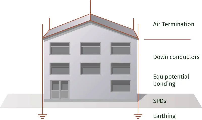
Figure 5: Structural Lightning Protection
Electrical & Electronic Systems within Structures (Part 4)
BS:EN 62305-4 sets out the rules for applying surge protection devices (SPDs) to protect the contents of the building from the secondary effects of lightning, and from internally generated switching transients.
Should the risk assessment dictate that a structural Lightning Protection System (LPS) is required, the system designer should always fit equipotential bonding Surge Protection Devices (SPDs). These are referred to as Lightning Current Arresters in our product selection pages.
If the assessment dictates that an LPS is not required, but there is an indirect risk that electrical services entering the structure could be affected, the designer should always fit SPDs.
A Lightning Protection system that employs the use of “structural Lightning Protection/Earthing” alone does not effectively protect electronic systems.
Effective protection is only achieved through the use of “coordinated SPDs”:
Type 1: lightning current arresters (tested with a 10/350μs waveform)
Type 2: surge arresters (tested with an 8/20μs waveform)
Type 3: surge arresters, fine protection (tested with an 8/20μs waveform)
BS:EN 62305-4 employs a principle of using Lighting Protection Zones (LPZ) to progressively reduce a potential 6,000 volt transient overvoltage to a safe voltage below that of the withstand voltage of the equipment to be protected. SPDs are located at the boundaries of these zones.
Kingsmill offer combined Type 1 + 2 SPDs as an easy and economical choice.
Kingsmill Surge Protection Devices are set out in the Surge Protection section.
Summary
A good Lightning Protection system must include:
Air Termination/Down Conductor System
- To intercept the lightning strike
- Comprises Air Terminals, conductors, Fixings and Clamps
Equipotential Bonding
- To minimise dangerous flashover from the Lightning Protection System to metallic/connective parts of the structure and its contents
- To route lightning current safely towards the Earthing System
Earth Network
- To safely dissipate the lightning current to earth
- Comprises Conductors, Earth Rods, Clamps and Bonds
Surge Protection
- To safely arrest any overvoltage carried through power and data lines as a result of lightning
- Comprises surge and overvoltage arresters