Protector Selection – 7 Steps
Where and how might one install a surge protection device?
In order to select a protector, the following information has to be determined:
STEPS 1 & 2 . . .
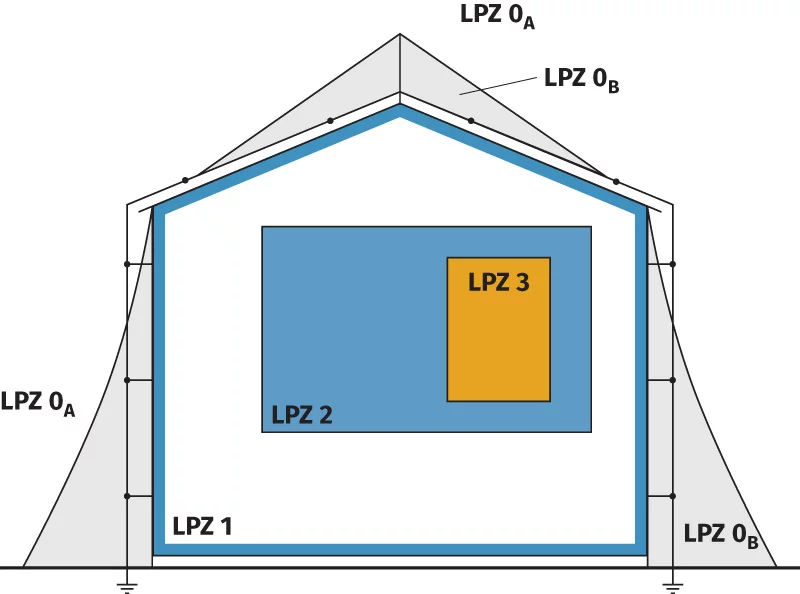
Lightning Protection Zones
BS:EN 62305-4 employs a principle of using Lightning Protection Zones (LPZ) to progressively reduce a potential 6,000 volt transient overvoltage to a safe voltage.
This voltage must be below that of the withstand voltage of the equipment to be protected.
SPDs are located at the boundaries of these zones.
STEP 3 . . .
Determine the voltage protection level
It is important that a protector does not ‘let through’ harmful voltages to the equipment that it is protecting. In the table below, “withstand level” equates to Up or voltage protection level. In the case of everyday electronic equipment, this is 1,500 volts.
Withstand voltage of the equipment being protected
Not only is it important to select an SPD that can withstand the current associated with the location in which it is to be placed, BUT It is also important that an SPD does not let-through to the equipment, a transient that is larger than the equipment’s withstand voltage.
Withstand impulse categories
Kingsmill mains protection devices have a let-through voltage of less than 1,500 volts therefore protecting Type I, II, II and IV electrical equipment (as defined above).
STEP 4 . . .
Selection of mains Surge Protection Devices
Once we have determined:
- The Lightning Protection Level (LPL) and Lightning Protection System (LPS), see Risk Assessment
- Whether a structural Lightning Protection System is required or not, and
- The lightning protection zones in which to locate the SPDs, together with the purpose of the SPD . . .
- The number of metallic services entering the structure
When evaluating the existence of a metallic service, it is important to establish whether it is continuous and provides a solid path to earth.
NOTE: some metallic services connect to non-metallic or insulating material close to the structure (ie water pipes, gas pipes, fibre optics etc).
Determine the size or kA rating of the required SPDs
Service entrance protection/equipotential bonding – Type 1 SPDs – lightning current arresters (mains supply)
Only Type 1 SPDs are selected using the LPL and LPS calculated from BS:EN 62305.
When lightning (200kA) strikes a building with structural lightning protection, it is assumed that 50% of the current (100kA) flows directly to earth through the building’s lightning protection conductors. The rest is assumed to flow through the metallic services. So, if there was only one metallic service supplying the building, 50% of the current (100kA) would be assumed to flow through it.
If that metallic service was a three phase electricity supply, then the 100kA would be equally split between each of the modes (lightning current flows to earth so, in a three phase system, there are four modes (or ways) in which lightning will flow – L1 to E; L2 to E; L3 to E and N to E – known as “common mode”).
If there is more than one metallic service entering a building, the 100kA is split equally between each service. If that second service happens to be a power supply, then it is further split by mode, as illustrated below:
| Lightning Protection Level (LPL) | Maximum Current kA (10/350 waveform) | Class of Lightning Protection System (LPS) | Maximum Current (50% of Current) | Maximum Current per Mode – 3 phase (L1, L2, L3, N, E) 4 wires + earth | Maximum Current per Mode – Single Phase (L, N2) 2 Wires + Earth | Maximum Current (25% of Current on Each Service) | Maximum Current per Mode – 3 Phase (L1, L2, L3, N, E) 4 Wires + Earth | Maximum Current per Mode – Single Phase (L, N) 2 Wires + Earth |
|---|---|---|---|---|---|---|---|---|
| l | 200 | l | 100 | 25 | 50 | 50 | 12.5 | 25 |
| ll | 150 | ll | 75 | 18.75 | 37.5 | 37.5 | 9.37 | 18.75 |
| lll & lV | 100 | lll & lV | 50 | 12.5 | 25 | 25 | 6.25 | 12.5 |
Illustration of the principle of division of current
Cautionary note – when taking water and gas pipes into account, it may be that at the point of entry to the building, they are metallic, BUT a short distance away they may be of non-conducting material, and therefore not reliable earths.
Only points where power, data and telecom cables enter or exit the building are sized in accordance with BS:EN 62305-4.
This includes the power supplies of roof mounted plant, external lighting, etc. In these cases the SPD should be placed as close as possible to the equipment or at the sub-distribution board supplying the equipment.
SPDs at these locations are known as Type 1 protectors and are tested with a 10/350µs waveform.
| Lightning Protection Level (LPL) | Maximum Current kA (10/350μs Waveform) | Class of Lightning Protection System (LPS) | Maximum Current One Metallic Service (50% of Current) | Maximum Current per Mode – 3 Phase (L1, L2, L3, N, E) 4 Wires + Earth | Maximum Current per Mode – Single Phase (L, N) 2 Wires + Earth | 3 Phase | Structure Type |
|---|---|---|---|---|---|---|---|
| l | 200 | l | 100 | 25 | 50 | KM1+2-25- series | Housing, commercial, industrial |
| ll | 150 | ll | 75 | 18.75 | 37.5 | – | – |
| lll & lV | 100 | lll & lV | 50 | 12.5 | 25 | KM1+2-12.5- series | Housing with no LPS fitted, class III & IV buildings, between buildings. |
If connected by overhead service
Type 1 SPD
Rated at 12.5kA per mode, we recommend the use of a combined Type 1+2 device, to ensure that electronic equipment is properly protected.
If connected by underground cable
Type 2 SPD
Since underground cables are not subject to direct lightning and thus see only partial lightning current. However, if the building has an aerial, satellite dish, A/C unit or PV array, which might act as a Lightning Conductor, we recommend using a Type 1+2 protector.
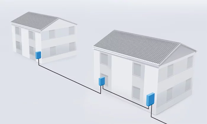
Protection between buildings
Where services exit one building and re-enter another building, Type 1+2 protectors should be used at the distribution board supplying the out-going circuit and again at the incoming distribution board of the next building.
The same would apply to data and telecommunication lines.
Our combined Type 1+2 SPDs are tested using both 10/350μs and 8/20μs waveforms.
Type 2 SPDs are tested with an 8/20µs waveform.
Internal protection – Type 3 SPDs – surge arresters – fine protection (mains supply)
Type 3 SPDs are located at socket outlets or switches supplying sensitive electronic equipment and are used to further reduce the size of transients that may affect electronic systems. Such devices are installed within 5m of the equipment to be protected.
Type 3 SPDs are tested with an 8/20µs waveform.
The Kingsmill range of mains power Surge Protection Devices is coordinated to allow ease of installation without the need for considering minimum cable inductance requirements.
STEP 5 . . .
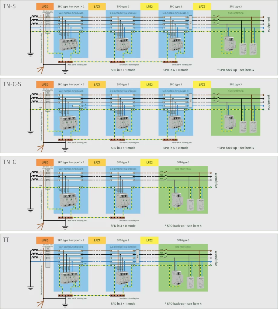
The next task before a final SPD part number can be selected, is to determine the earthing system used in the building. This will be either TN-S, TN-C-S, TN-C or TT.
The differences between the various systems are in how the Neutral and Earth conductors enter the building, and whether, as in the case of TN-C-S. A combined Neutral and Earth, is separated out in the Main Distribution Board.
Determine the installation’s Earthing System
Connection Type – definition
It is important to select the correct SPD for both its location as well as purpose. Kingsmill mains protector part numbers are made from a number of elements:
| KM | = | Kingsmill |
| 1+2, 2+3 | = | Lightning Protection Level |
| 25, 12.5 & 10 | = | kA per mode |
| x + 0 and x + 1 | = | connection format for the modes (see the explanation, below) |
| SC | = | remote contacts for signalling (included as a standard feature) |
| eg | = | KM1+2-25-4+0 SC |
SPDs are factory configured in two connection formats, CT1 (x+0) and CT2 (x+1). These are shown below:


In the case of the x + 0 or CT1 connection the phase L1, L2, L3 and neutral conductors are connected to earth via the SPD. These are lightning current or equipotential bonding SPDs, whose primary purpose is to guard against the effects of lightning surges. Such surges appear as phase conductor and neutral conductor to earth, known as “common mode”.
Common mode surges are larger in magnitude than differential mode (switching) and can result in flashover and insulation break-down if the voltage withstand voltage (see Table 1) is exceeded.
Hence, lightning equipotential bonding SPD’s protect in common mode.
In the case of the x + 1 or CT 2 connection the phase conductors (L1, L2 & L3) are connected to earth via the SPD module connecting the neutral to earth. These devices are associated with switching and appear as line to line or line to neutral surges, known as “differential mode”. The neutral conductor module is rated for the full kA rating ie for LPLI that’s 100kA.
It can be seen from the earthing system diagrams (on page SPD:17) that different connection types are used in different applications.
Connection Type – Selection
TN-S/TN-C-S systems
Type 1 or combined Type 1+2 SPDs are placed at the service entrance for the incoming supply (main distribution board). These devices protect against the effect of lightning electromagnetic impulses. The devices are ALWAYS connected in the x+0 (or CT1 format), with phase and neutral conductors connected to earth via the SPD.
In the case of Type 2 protectors located at downstream sub-distribution boards, a choice can be made:
- The SPD can be in the x+0 (CT1 connection type) – to further reduce the effects of lightning electromagnetic impulses, or it can be
- Connected in the x+1 (CT2 connection type) to restrict transient overvoltage generated internally, for example, from switching overvoltages.
In commercial and residential buildings it is better to select Type 2 SPDs in the x+0 mode, but in industrial complexes, due to switching overvoltages, it is better to select the x+1 (CT2 type).
Devices installed before the neutralising point in TN-C-S (4 wire) would require 3+0. Devices to be installed after the neutralising point (5 wire) would require 4+0.
TN-C system
In TN-C systems, Type 1, combined Type 1+2 and Type 2 protectors can only be connected in the x+0 format.
TT system
TT supply networks, in which only neutral conductors – L1, L2, L3 – are routed from the power source.
All protector types should ALWAYS be connected in the x+1 format.
STEP 6 . . .
Protective Distances
We learnt from Steps 4 and 5 that protectors need to be installed at the service entrance position and as close as possible to the equipment being protected.
If the distances between SPDs or the SPD and the equipment being protected are too long, reflected voltages may appear on the line which could destroy the connected equipment or cause breakdown of the cable insulation. Such reflections can cause the up-stream SPD “let-through voltage” or Up (voltage protection level) to double. This effect occurs if the equipment is disconnected inside or its input impedence is high.
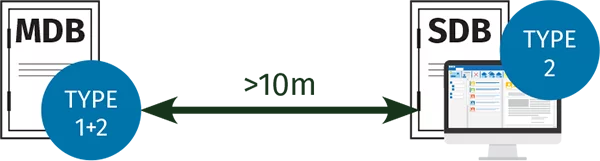
If the distance between the SPD and the equipment being protected is less than 10m, such reflections can be ignored. However, if the distance is greater than 10m additional SPDs must be installed.
Type 1+2 Devices
CABLE LENGTHS BETWEEN 10M AND 50M:
If the cable length between the Type 1+2 SPD and the SDB or electronic equipment being protected is >10m, a Type 2 SPD must be installed downstream of the Type 1+2 SPD.
CABLE LENGTHS OVER 50M:
If the cable length between the SPD and the SDB or electronic equipment being protected >50m, we recommend a Type 1+2 device with In= 30kA (8/20μs) is fitted. This will work as a strong Type 2 SPD protector, coping with transient overvoltages and different earth potentials (particularly if the equipotential bonding of earths is not continuous).
Install at the nearest convenient SDB or switched fuse supplying the equipment. This SPD must be located less than 10m away from the equipment being protected.

Cable lengths >50m and <100m = 12.5kA rated SPD Cable lengths >100m = 25kA rated SPD
TYPE 2 DEVICES:
CABLE LENGTHS OVER 10M:
If the cable length between the Type 2 SPD and the next downstream SDB or the electronic equipment being protected is >10m, additional protection is required.

TYPE 3 DEVICES:
Type 3 SPDs offer a further level of protection, where sensitive or high value equipment is deemed to require an extra level of protection. Such devices, whether installed with a Type 1+2 SPD or a Type 2 SPD, would be installed within 10m of the Type 1+2/2 SPD and as close as possible to the equipment being protected. Type 3 SPDs must be installed no further than 5m away from such equipment.
Two types of device are available: one which can be incorporated into an SDB or its own enclosure (KM3-10-3+1 SC and KM3-10-1+1 SC) and one which can be wired into the switch socket itself as a retrofit item (KM3-275-A).
If fine protection is required, a Type 3 protector should be fitted as close as possible to the equipment being protected and no more than 5m of cable length away.

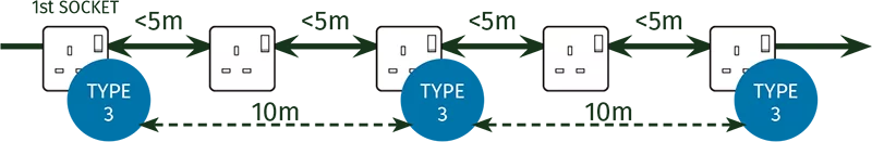
When using the Type 3 socket outlet protector (KM3-275-A), the protector should always be installed at the first socket outlet downstream of the distribution board supplying it and thereafter every 10m of circuit length.
STEP 7 . . .
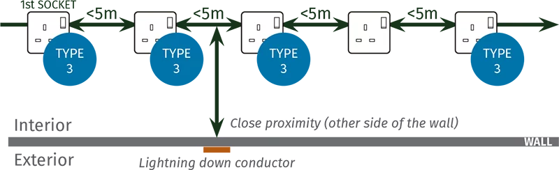
Assess cable routeing and other considerations
Cable routeing and the connection of SPD’s can affect the performance of the SPD and the level of protection that it can provide:
- Cable routeing should avoid proximity to lightning protection down conductors
- Large inductive loops between communication and power cabling should be avoided
- Cable screening should be considered
- Connecting leads must be as short as possible
Avoid long distances (over 10m) between the SPD and the equipment being protected to avoid oscillations
- Examine use of electromagnetic shielding on cables
- Determine locations of distribution boards and the connected equipment to be protected
- Determine length of circuit cables