Spacing and Installation
Device Spacing
Spacing between Surge Protection Devices and the electronic equipment (eg computers/control systems/smart TVs etc) to be protected is crucial for achieving effective protection levels. The transient let-through voltage of the protector (the amount of voltage that leaves the SPD) can be magnified due to the effect of oscillation on cable lengths of over 10m.
Below is a guide for the effective spacing of additional SPDs.
Type 1+2 Devices
If the cable length between the Type 1+2 SPD and the SDB or electronic equipment being protected is >10m, a Type 2 SPD must be installed downstream of the Type 1+2 SPD.
CABLE LENGTHS OVER 50M:
If the cable length between the SPD and the SDB or electronic equipment being protected >50m, we recommend a Type 1+2 device with In= 30kA (8/20μs) is fitted. This will work as a strong Type 2 SPD protector, coping with transient overvoltages and different earth potentials (particularly if the equipotential bonding of earths is not continuous).
Install at the nearest convenient SDB or switched fuse supplying the equipment. This SPD must be located less than 10m away from the equipment being protected.


Cable lengths >50m and <100m = 12.5kA rated SPD Cable lengths >100m = 25kA rated SPD
Install at the nearest convenient SDB or switched fuse supplying the equipment. This SPD must be located less than 10m away from the equipment being protected.
TYPE 2 DEVICES:
CABLE LENGTHS OVER 10M:
If the cable length between the Type 2 SPD and the next downstream SDB or the electronic equipment being protected is >10m, additional protection is required.

TYPE 3 DEVICES
Type 3 SPDs offer a further level of protection, where sensitive or high value equipment is deemed to require an extra level of protection. Such devices, whether installed with a Type 1+2 SPD or a Type 2 SPD, would be installed within 10m of the Type 1+2/2 SPD and as close as possible to the equipment being protected. Type 3 SPDs must be installed no further than 5m away from such equipment.
Two types of device are available: one which can be incorporated into an SDB or its own enclosure (KM3-10-3+1 SC and KM3-10-1+1 SC) and one which can be wired into the switch socket itself as a retrofit item (KM3-275-A).
TYPE 3 SPD LOCATION:
If fine protection is required, a Type 3 protector should be fitted as close as possible to the equipment being protected and no more than 5m of cable length away.

TYPE 3 SOCKET OUTLETS:
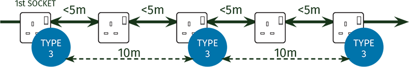
When using the Type 3 socket outlet protector (KM3-275-A), the protector should always be installed at the first socket outlet downstream of the distribution board supplying it and thereafter every 10m of circuit length.
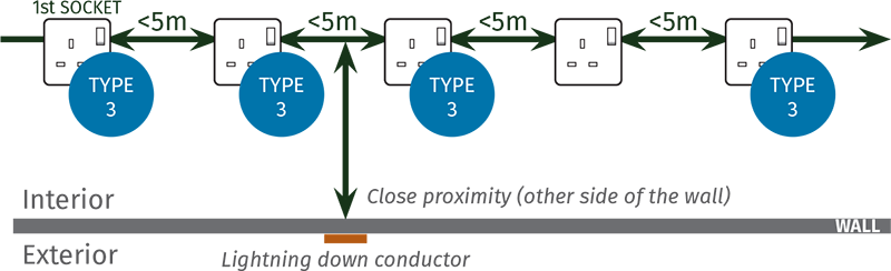
SOCKET OUTLETS FITTED ADJACENT TO STRUCTURAL LIGHTNING PROTECTION:
However, if the socket outlet circuit is running on the inside of a wall that has a down conductor fitted to the outside, each socket outlet within 5m of the down conductor position should be protected individually with KM3-275-A protectors.
Installation Guide
TN-C-S Neutralising Point
When installing SPDs to distribution boards with a TN-C-S earthing arrangement, it is important to establish where the neutralising point of the PEN is located. Typically, the neutralising point will be at the origin of the installation before the main supply fuse, therefore a TN-S type SPD is to be installed after the neutralising point. However, if the device is to be installed before the neutralising point, a TN-C type device should be installed.
Installation
When installing SPDs, there are 3 main considerations:
- Back up OCPD (Over Current Protection Device)
- Conductor sizing
- Conductor length & routeing
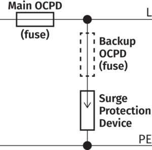
Back Up OCPD
When installing SPDs, the requirement for an OCPD depends on two main factors:
- The main OCPD rating of the distribution board
- The backup OCPD rating of the SPD
The typical maximum back up OCPD required for Kingsmill SPDs is 160A (250A for LPL I&II SPDs).
If main OCPD ≤ recommended maximum backup OCPD of the SPD, a supplementary OCPD for the SPD is not required.
If main OCPD rating > maximum backup OCPD rating of the SPD, a backup OCPD is required.
*If a backup OCPD is required, the recommended maximum backup OCPD should be installed.
Conductor Sizing (as per BS 7671:2018, 534.4.10)
“Conductors between SPDs and the main earthing terminal or protective conductor shall have a cross-sectional area not less than:
– 16mm² copper or equivalent for Type 1 devices installed at or near the origin of the installation
– 6mm² copper or equivalent for Type 2 devices installed at or near the origin of the installation
Referring to Regulation 433.3.1(ii), conductors connecting SPDs and the OCPDs to live conductors should be rated to withstand the prospective short-circuit current to be expected and shall have a cross-sectional area not less than:
– 6mm² copper or equivalent for Type 1 devices installed at or near the origin of the installation
– 1.5mm² copper or equivalent for Type 2 devices installed at or near the origin of the installation”
Conductor Length & Routeing
Conductor Length & Routeing
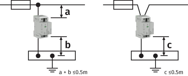
For SPDs to efficiently discharge any overvoltages to earth, the connected conductors to the SPD should be as short and straight as possible.
Therefore, conductor lengths should be kept to a minimum and not exceed a total of 0.5m (X).
If this is not achievable, you can increase the PE conductor length to 0.5m by installing the device in a ‘V’ connection (Y).
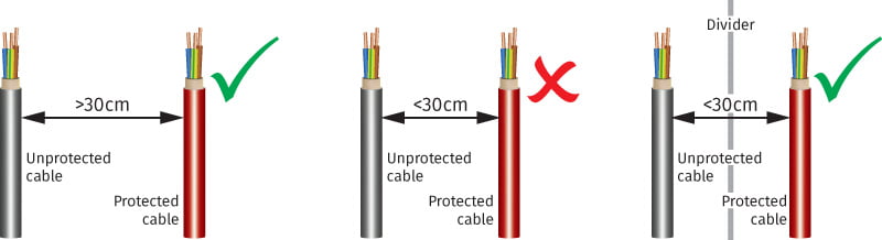
Conductors should be routed so as not to induce any overvoltages from unprotected (dirty) onto protected (clean) lines.
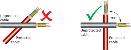
Care should be taken to keep conductors straight and to minimise conductor loops. The crossing of protected and unprotected conductors should also be avoided.