Solar Tubular Batteries

Solar Tubular Batteries

SKU: N/A Category: Tag:
Download PDF

SKU: N/A Category: Tag:

Product Information:

These lead tubular batteries use premium technology and high grade materials to deliver maximum power for extended durations and have an appreciably longer life span. These batteries are specifically suitable for powering up UPS and inverters. These flooded lead acid batteries are environment-friendly, highly reliable in performance and are low in cost. Hear again our extensive research and development wing has helped us create batteries customized to suit Indian operating conditions. These flooded batteries are perfect for use in battery powered vehicles and to power inverters as well as for telecom use.

Features:

  • Long shelf life when left unattended for extended periods
  • Pasted negative plates
  • Tubular positive plates
  • Acid resistant polyestor guantlets
  • High porosity envelope seperators
  • Micro porous ceramic vent plug

More Information:

Product Benefits:
  • Long design life
  • Very low maintenance
  • Can handle extreme weather conditions
  • Rugged performance
  • Longer life without charging
  • More efficient and saves money

Discharge & Charge Scenario (80%DOD) CYCLE METHOD

Discharge with 2I10 for 4 hours (80% DOD), charge with 2I10 for 3.5 hour + I10 for 0.5 hour + 0.25I10 for 3.5 hour. This is one cycle.

RESIDUE CAPACITY DETERMINATION

The batteries are discharged at 10 hour rate aer every 50 cycles to test battery capacity. When residue capacity of 10 hour rate capacity is lower than 80%, test is ended. Aer discharge at 10 hour rate aer every 50cycles, the charge method is: charge 80% of discharged capacity with current of 2I10 + charge 20% with current of I10 + charge 20% with current of 0.4110 (i.e. charge 120% of discharged capacity)

TEMPERATURE – 27OC

Advantage of Upper Constant Current Charge Model Battery; can be completely recharged within 8 hours. The end charge voltage will be higher than 2.6Vpc, which is good for active material exchange. Disadvantage of Upper Constant Current Charge Model It has risk of battery malfunction without voltage limited. It isn’ easy to manage charging in practice.

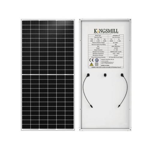
Solar panels are a clean source of energy that use the sun’s rays to convert them into electricity or heat.

Our clean energy solutions provide electrical power as a way to decarbonize and transition to clean energy in our mission to combat climate change.

Capacity at 27 deg C When discharged at (C20 upto 1.75 VPc 1.280)DIMENSIONS L x W x H (±3mm)Weight ( Dry x Filled)Initial Charge Minimum AH Input (AH)
Initial Charge at Constant Current (A) Start (Upto 2.3Vpc)
Initial Charge at Constant Current (A)-Finish (Upto 2.75Vpc)Constant Potential Limiting Current (Amps)Triple Charge Current in (mA)(min x max)Model
150 AH
505 x 190 x 41029 x 56157.5

525

25

130 x 520KMASTB16500
200 AH
505 x 190 x 41029 x 6120963030155 x 625KMASTB22000
240 AH
505 x 190 x 41034 x 68241177036.6190 x 765KMASTB26000

* The height mentioned is upto terminal top

INITIAL CHARGING INSTRUCTION FOR DRY CHARGE BATTERY

1) Filling in specific 1.220 ± 0.005 at 27 deg C
2) Rest Period 12 hrs
3) In order to reduce the charging time, the following route may be adopted
For ASTB 22000 The initial 2.36Vpc charging current may be 20A upto followed by 9A upto 2.75Vpc
For ASTB 26000 The initial 2.36Vpc charging current may be 24A upto followed by 11A upto 2.75Vpc

CONDITION OF FULLY CHARGED

A) 3 Consecutive hourly reading of specific gravity and voltage become constant
B) Top of charge voltage will be around 16.2V – 16.5V
C) All Cells should be gas freely
D) Minimum Ah has been given
5) Specific Gravity at fully Charged condition 1.240 ± 0.005 at 27 Deg C