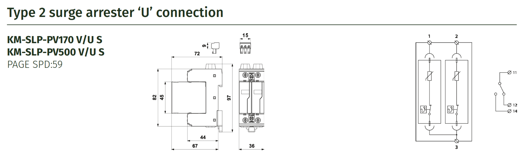
Product Information:
Surge arresters for use in photovoltaic systems with ‘U’ connection. Protects both poles.
Features:
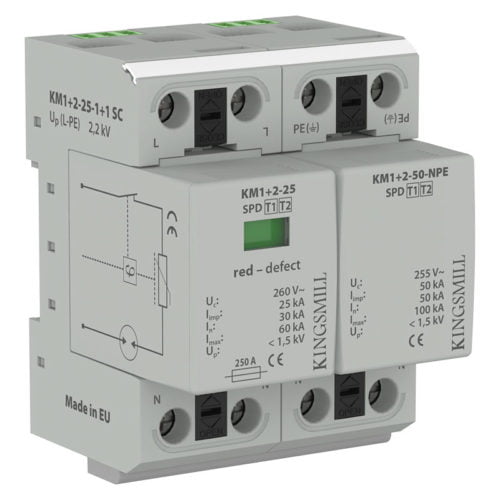
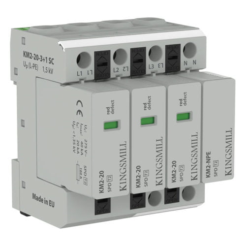
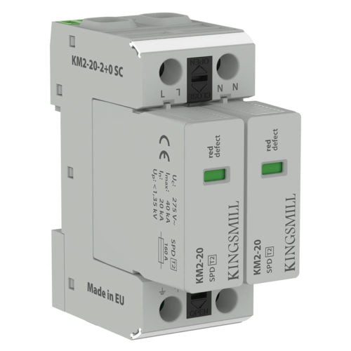
- Pluggable module
- Visual fault signalling
- Module locking
- Remote fault signalling
Benefits: Ideal for use with photovoltaic systems where the separating spark-over distance is without a Lightning Protection system.
Standards: EN 50539-11
Application: Use on Photovoltaic Systems up to 170 volts and 510 volts.
More Information:
Photovoltaic (PV) arrays and their associated equipment are expensive assets to purchase and so the need to protect them from the effects of lightning is of paramount importance.
A lightning surge protection device prevents damage to electrical and electronic equipment from transient over-voltage events by blocking or redirecting surge current to the ground instead of passing through the equipment.
Kingsmill has a range of Earthing, Structural Lightning Protection and Surge Protection products that can be used to provide protection against both the direct and indirect effects of lightning. Products relating to Earthing and Structural Lightning Protection are dealt with in their respective sections.