LED Street, Industrial and Security Lighting Protection
Why protect?
Public lighting systems, street lighting for example, as well as lighting for large industrial premises, can be extensive, with cable lengths running into hundreds of metres.
Such systems are exposed to risks of overvoltages induced by lightning strikes, as well as switching events.
Transient overvoltages in extensive installations may reach values that are higher than the specified withstand voltage of the light source (luminaire), thus leading to damage.
BS:EN 62305-2 sets out the sources of damage to installations: S1 Direct lightning strike to the installation. S2 Lightning strike within the proximity of the installed equipment, switching phenomena in MV and HV grids near to the installation. S3 Direct lightning strike to the connected mains supply. S4 Lightning strike near to the connected mains supply.
The standards IEC 60364-5-53 Chapter S34 and IEEE C62.41.2 also recommend the fitting of SPDs at the power input of an electrical installation.
Application of SPDs in lighting installations
LOCATION: connection of street lighting cables to the mains supply distribution board
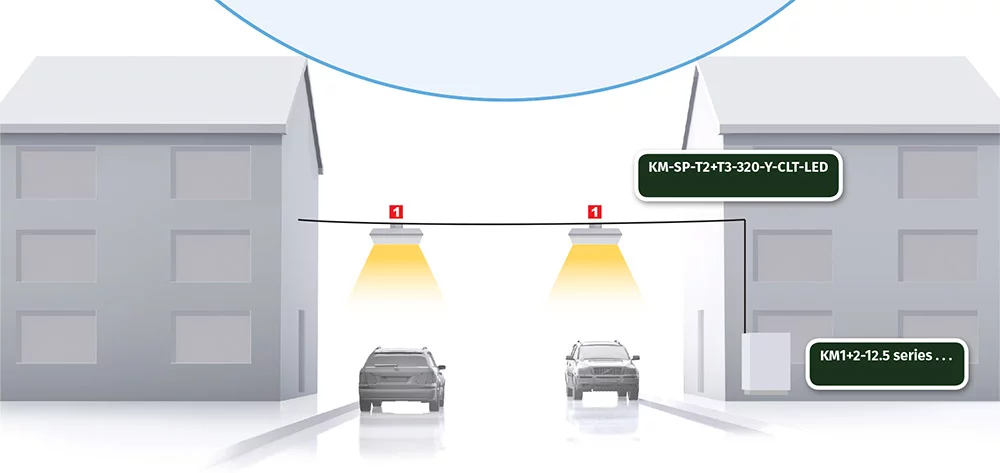
A Combined Type 1 & 2 lightning current and surge arrester is connected to the main distribution board (MDB). Where the supply to the MDB is via an overhead line, it is advisable to use the KM1+2-25- series (for the maximum expected kA per mode of 25kA). Where the MDB is supplied by underground cables it is possible to use the KM1+2-12.5- series. click here for tables defining the maximum kA that would be expected to appear per mode on a 3 phase system, resulting from lightning activity.
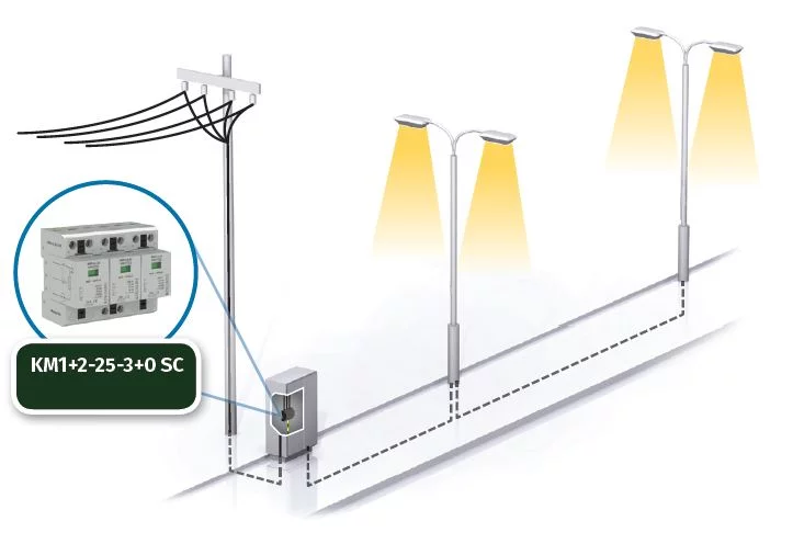
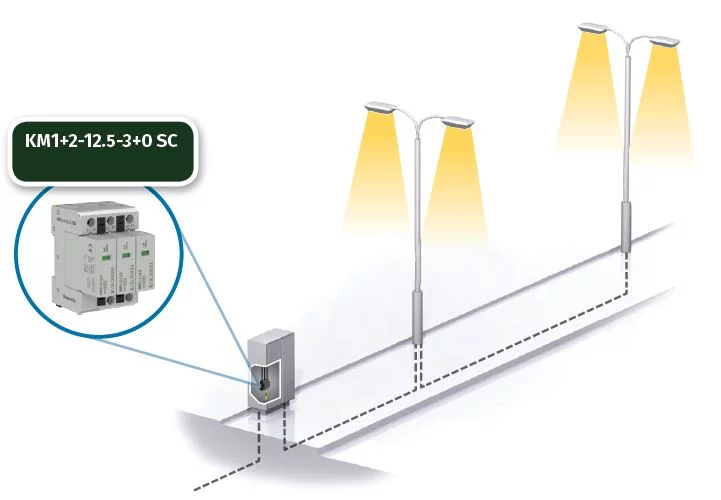
Where fluctuating voltages exist, or where the voltage might exceed the normally specified tolerance, and in places where the disconnection of load causes a voltage increase (ie during the night), it is advisable to use an SPD with a higher Uc (maximum operating voltage) or SPD’s where the switching and limiting elements are connected in series – MOV & GDT technology. In this latter case the Kingsmill products are the KM1+2-25- series and the KM1+2-20… VB series.
LOCATION: where the lighting system is prone to the effects of direct lightning strikes
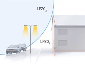
Where the height of the lighting column exceeds that of the surrounding buildings the luminaire is, in effect, situated in lightning protection zone LPZ0A, where the risk of direct lightning strike (S1) is present. Similarly, if the Lighting Column is outside the protective area afforded by a building’s Lightning Protection System, the luminaire is effectively in zone LPZ0A. In both cases the application of Surge Protection Devices are recommended.
Lighting at sports stadiums requires a higher Lightning Protection Level (LPL) to be considered, in addition to the installation of lightning conductors.
Street lighting in urban locations may be considered to be of Lightning Protection Levels III or IV, where the maximum current per mode on a three-phase system would be 12.5kA.
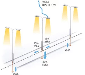
BS:EN 62305 assumes that 50% of the current in a direct lightning strike will be diverted to earth.
The remaining 50% will be split equally across connected conductive metallic pathways – in this case, the cables supplying the street lighting.
Lightning seeks a path to earth (common mode) and the current, is further sub-divided by the number of modes (in a three phase supply, these are L1 to E; L2 to E; L3 to E and N to E).

In many cases, street lighting is supplied from a three-phase cable. However, at the individual lighting column only one phase is connected to the luminaire and its control gear.
The street lighting distribution board would be fitted with a three-phase SPD and the individual lighting column with a single phase, 12.5kA per mode (25kA total discharge) SPD – our KM1+2-12.5-1+1 SC. (The diameter of most lighting column bases is usually large enough to accommodate the size of the SPD.)
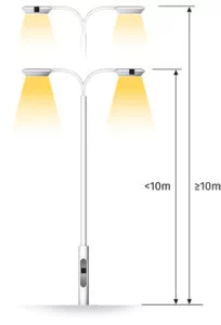
Where the cable length from the SPD mounted in the lighting column base, to the luminaire, exceeds 10m in height, then IEC 61643-12 dictates that an additional SPD is installed at the luminaire.
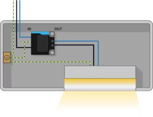
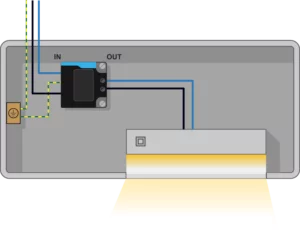
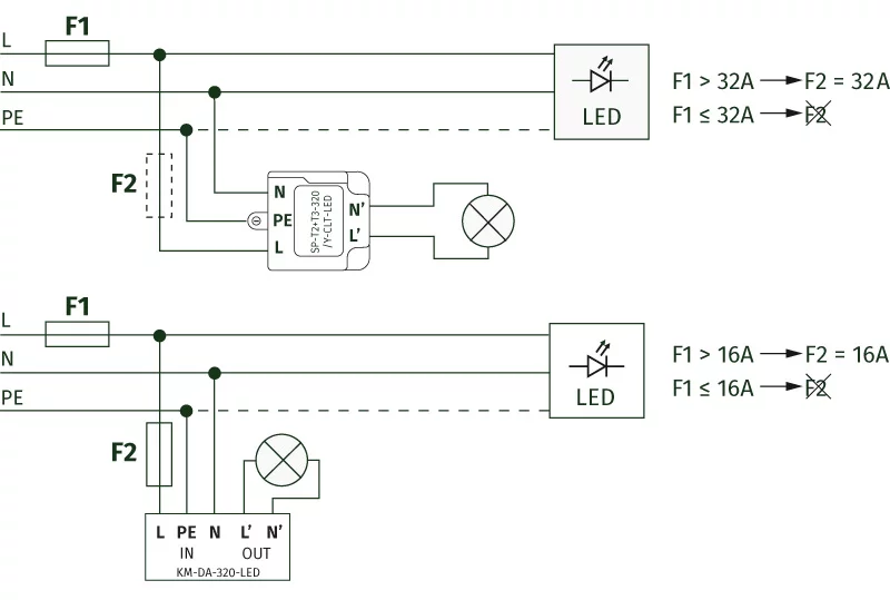
Our KM-SP-T2+T3-320/Y-CLT-LED (where the distance is less than 10m use the KM-DA-320-LED) is suitable.
LED systems can also be affected by induced voltages if the street lighting circuit is in close proximity to MV and HV cables.
SPDs are also required in such applications.
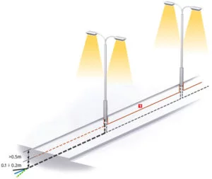
In addition, the installation of a buried earth conductor, earthed at both ends, can also help reduce the effect of voltages induced in this way.
LOCATION: protecting an industrial lighting system from induced voltages, resulting from lightning
Transient overvoltages can be induced on the cables supplying lighting through resistive coupling, inductive coupling and electrical switching.
More details.
Such overvoltages might harm the sensitive electronics used in controlling modern day LED luminaires.
SPDs are installed at the MDB and SDB locations as previously described in addition to the individual lighting circuits.
In the case of lighting installed under the roof of an industrial complex, eg high bay lighting, it is advisable to avoid parallel routeing of cables with lightning conductors. If such routeing is not possible, then it is recommended to fit an SPD at each luminaire (our KM-SP-T2+T3-320/Y-CLT-LED).
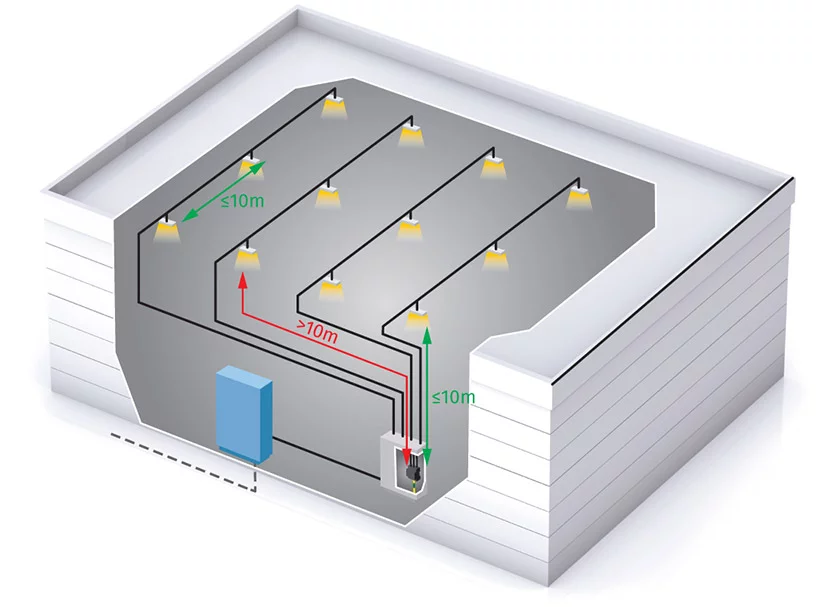
- The KM-DA320-LED is used where the first LED luminaire is ≤10m from the SPD in the distribution board supplying that circuit. Additionally, a KM-DA-320-LED is fitted for every 10m of lighting circuit thereafter.
- In the case that the first LED luminaire is located ≥10m away from the SPD protecting the distribution board supplying that circuit, a KM-SP-T2+T3/320/Y-CLT-LED is installed. Thereafter, for every 10m of lighting circuit a KM-DA-320-LED would be fitted.
Features and Benefits
Failure of the KM-SP-T2+T3-320/Y-CLT-LED is also indicated by darkened display openings, to identify the failure in the case of disconnected power supply.
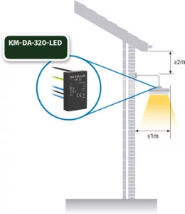
The SPD should be fitted as close as possible to the luminaire.
Comply with the requirements of IEEE (ANSI) C62.41.2 – C location – located externally.
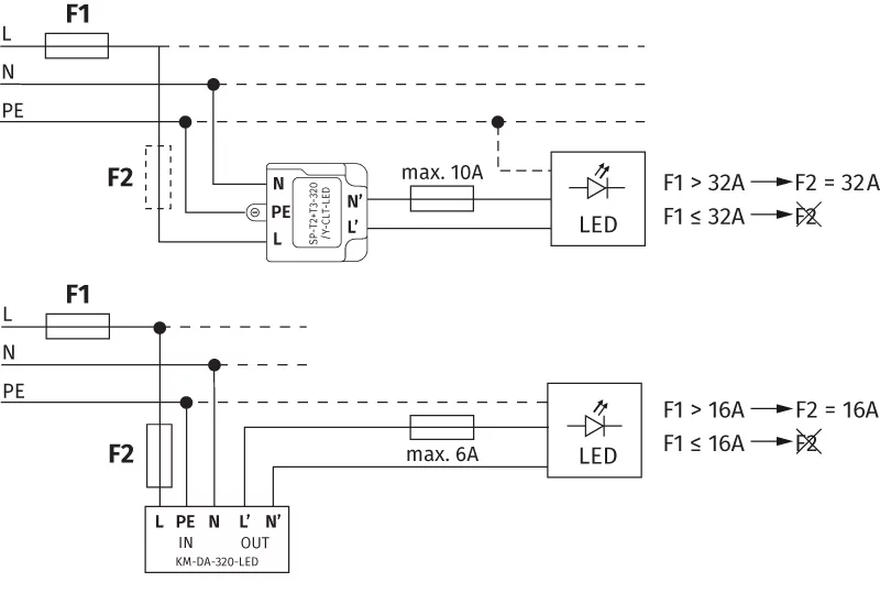
The internal connections of the KM-DA-320-LED and KM-SP-T2+T3-320/Y-CLT-LED are symmetrical, meaning that if phase and neutral is crossed, this does not affect the SPD.
The SPDs can also be used where luminaires are connected between phases, provided that the Uc maximum operating voltage is not exceeded.
The KM-SP-T2+T3-320/Y-CLT-LED earth terminal is a lug. The screw connecting the lug to the PE conductor, could also be used to secure the SPD to the luminaire.
An auxiliary plastic adapter makes it possible to the SPD to a 35mm DIN rail (TH 35), provided that the latter is not equipped with a lug to connect to the PE conductor.
