Effective earthing system is essential to ensure the safety of people and reliable operation of the whole group of electrical installations. Different parameters should be initially verified so that they do not exceed the tolerable limits. These parameters mainly include the earthing resistance/impedance, touch voltage and step voltage [1].
Other parameters may be also considered such as the lifetime of the earthing system and its resistance against corrosion.
Fig. 1 illustrates a graphical representation to show the step and touch voltages.
The step voltage is the potential difference (p.d.),
on the earth surface, that is experienced by an
operator bridging a 1m distance without contacting
any earthed structure.
By analogy, the touch voltage is the p.d. between the earth potential rise of an earthing system and the surface potential where a person could be standing while at the same time having a hand in contact with (an) earthed structure(s).
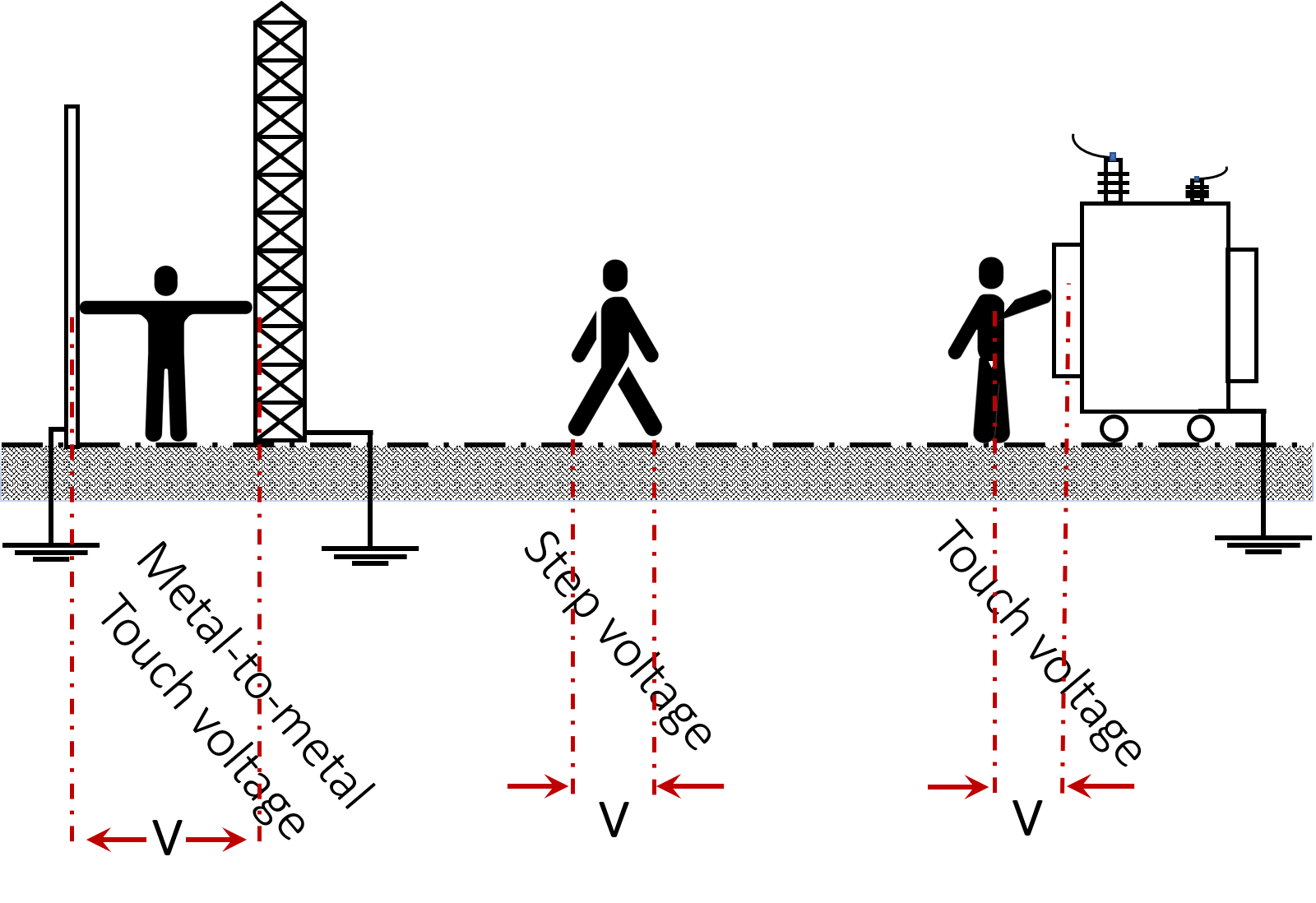
Metal-to-metal touch voltage usually occurs when metallic objects or structures within the substation site are not bonded to the earthing system [1,2].
During a lightning discharge or over-voltages, fault currents dissipate into the earth through the grid and other earth electrodes. The resulting potential gradients have a primary effect on the value of the p.d. (denoted V), which depends on the soil resistivity and the earthing system configuration. Using the value of tolerable body current, one can determine the tolerable voltage between all points of contact, thus, the step and touch voltages [1—3].
CDEGS and CYMGRD are two examples of commercially available software to compute the step and touch voltages based on surface potential distribution and gradient.
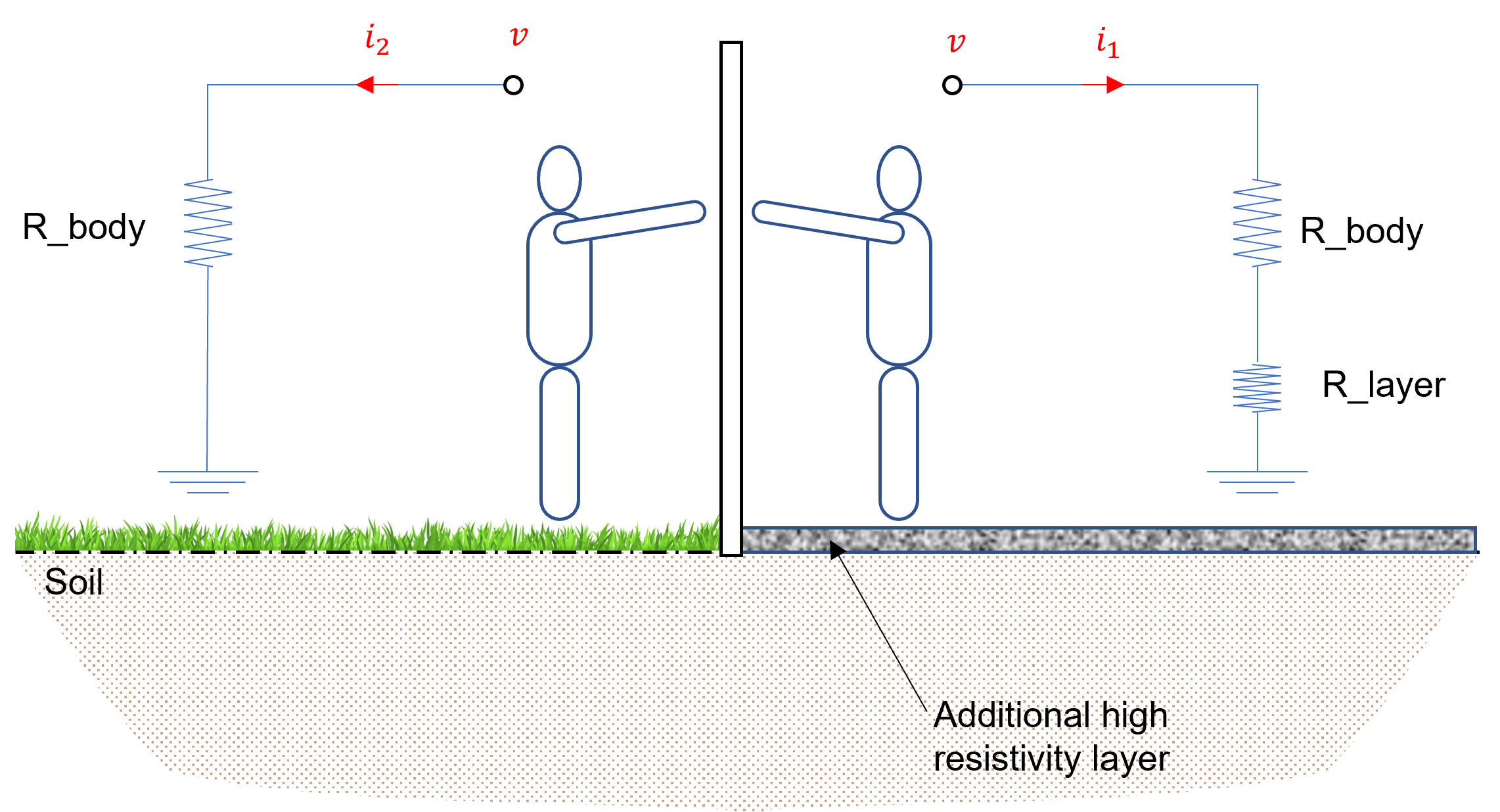
It is a common practice to have an upper layer of high resistivity material overlaying the earthed area of a substation. This additional layer, usually of gravel, is used to increase the contact resistance between an operator’s foot and the earth surface, giving a maximum allowable body current and considerably higher step and touch voltages.
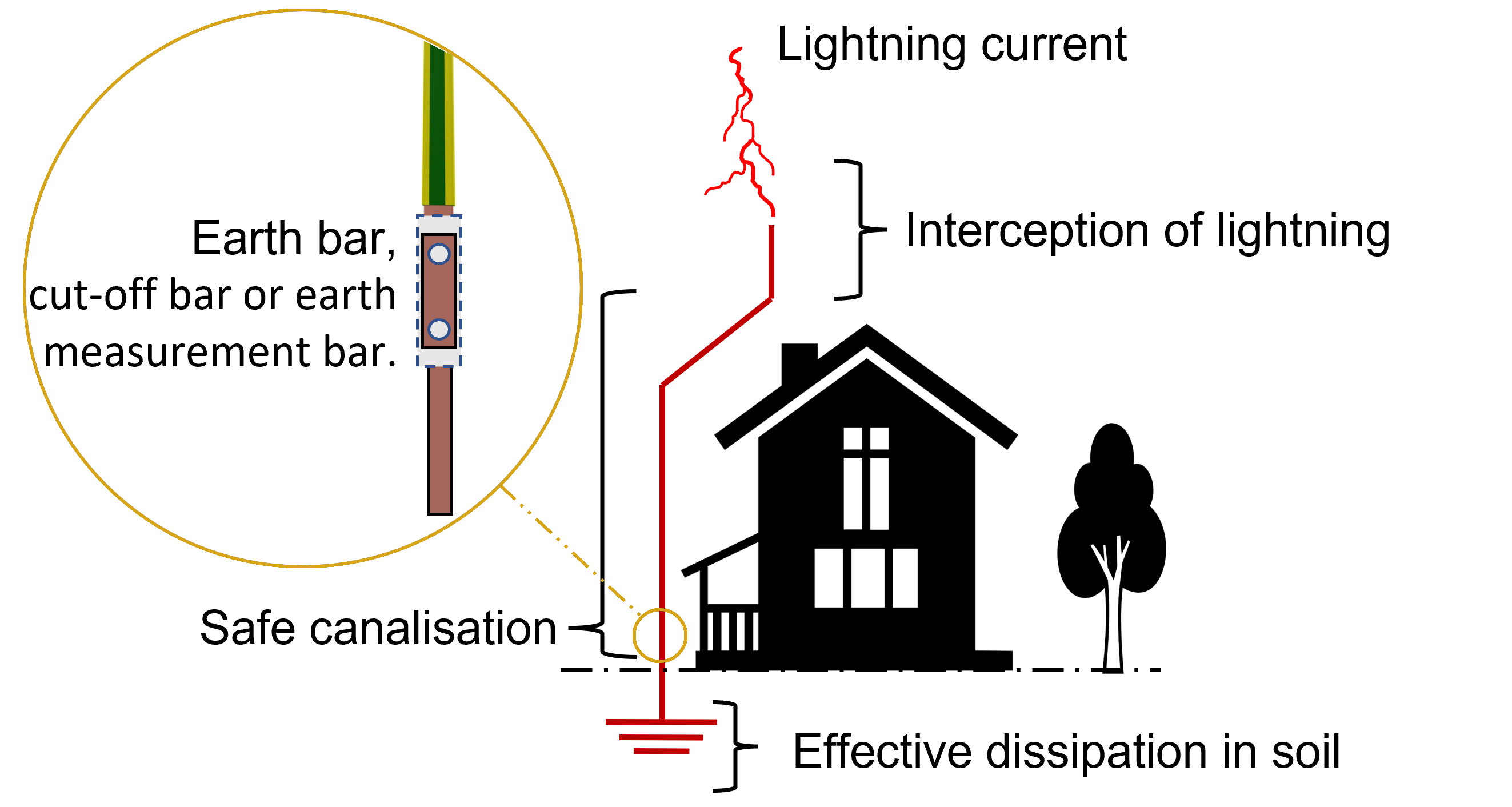
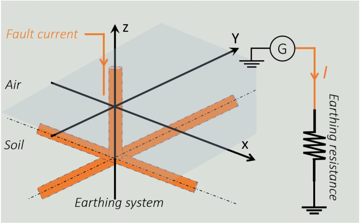
Earthing systems (vertical and horizontal conductors, grids, · · · etc.) ensure the safety of people and equipment. They are designed to provide a low impedance path, allowing low frequency fault currents or high frequency transients to effectively flow into the earth. Most soils behave both as a conductor of specific resistance and as a dielectric. Except for high-frequency waves penetrating the earth, the charging current is negligible in comparison to the leakage current, and the earthing system can be represented by a pure resistance as represented in Fig. 2.
The smaller the value of the earthing resistance, the easier the current dissipation through the earthing system. This resistance mainly depends on the geometric shape of the system itself, its electrical properties and the characteristics of the surrounding environment. Various mathematical expressions are developed to calculate the approximate earthing resistance of different configurations [1].
Indeed, the earthing resistance depends closely on the cross section of the conductors constituting the earthing system. IEEE std 80 provides expressions to estimate the section of down conductors and that of buried conductors.
It is required to install an earthing system with resistance so low as to assure that the rise of a ground potential will not generate surface gradients unsafe for human contact. According to [2], a continuous conductor loop should surround the perimeter to enclose as much area as practical. This measure helps to avoid high current concentration and, hence, high gradients both in the grid area and near the projecting cable ends. Enclosing more area also reduces the resistance of the earthing system.
Soil analysis should be performed for a better selection of a conductive material that is compatible with the nature of the soil, considering its thermal stability, its resistivity against corrosion, its conductive performance and of course its cost.
Subjected to high frequency and transient currents, such an earth system exhibits a behaviour significantly different from that at low frequency due to the presence of the reactive component and certain additional phenomena, namely soil ionization, mutual coupling as well as the frequency dependence of the soil electrical parameters.
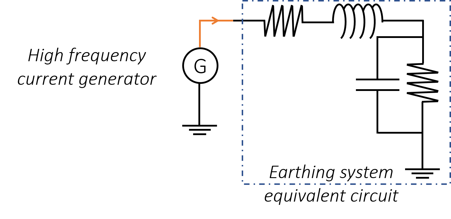
For instance, the vertical earth electrode at high frequency can be modelled as a lumped RLC circuit as shown in Fig. 3. An inductance and capacitance have been used to complete the equivalent circuit model. Multiple equations and equivalent circuits have been produced and examined in the literature, and Fig. 3 shows the equivalent circuit for a vertical rod subjected to high frequency currents.
Indeed, such an approximation is only sensitive for the study of interactions with objects of electrically small dimensions. This is not the case for earth systems, because they are relatively long compared to the wavelength of the external fields generated by lightning (i.e., the minimum wavelength corresponding to the highest frequency component ). To this end, the earth electrodes must be analyzed by dividing them into numerous small elementary segments.
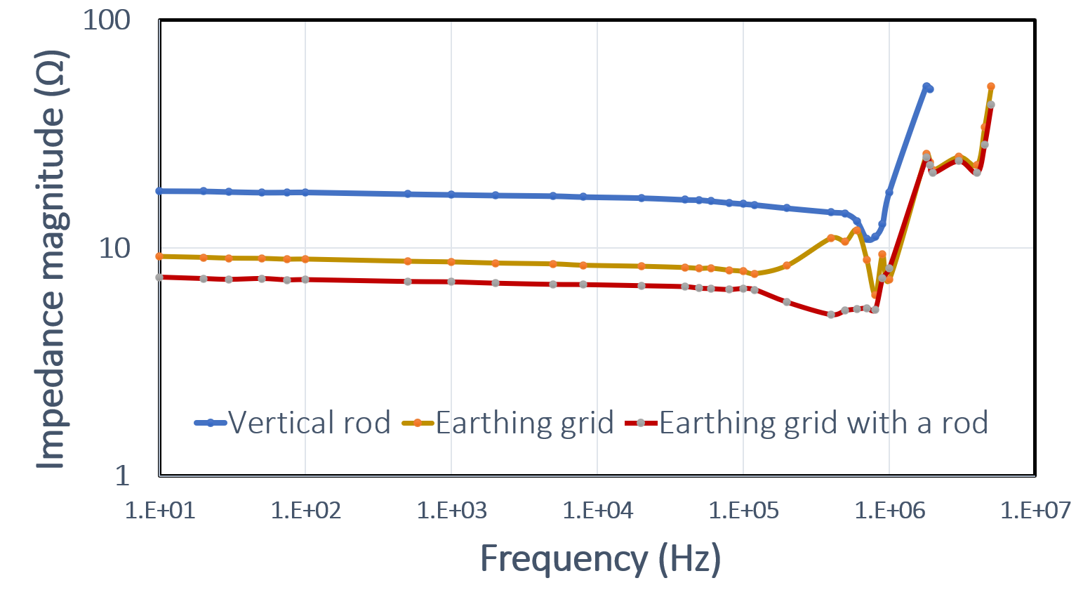
Despite the large number of modelling approaches proposed in the literature, the assurance for the effectiveness of any earthing system may be verified by periodically measuring its earth resistance. Fig. 4 shows the measured earthing impedance of vertical rod, earthing grid and earthing grid with vertical rod. These systems are subjected to currents of variable frequency up to 10MHz.
There are several methods for measuring resistance
of earthing systems. Among them, the fall-ofpotential method is widely applied for almost all
types earthing systems [2,3].
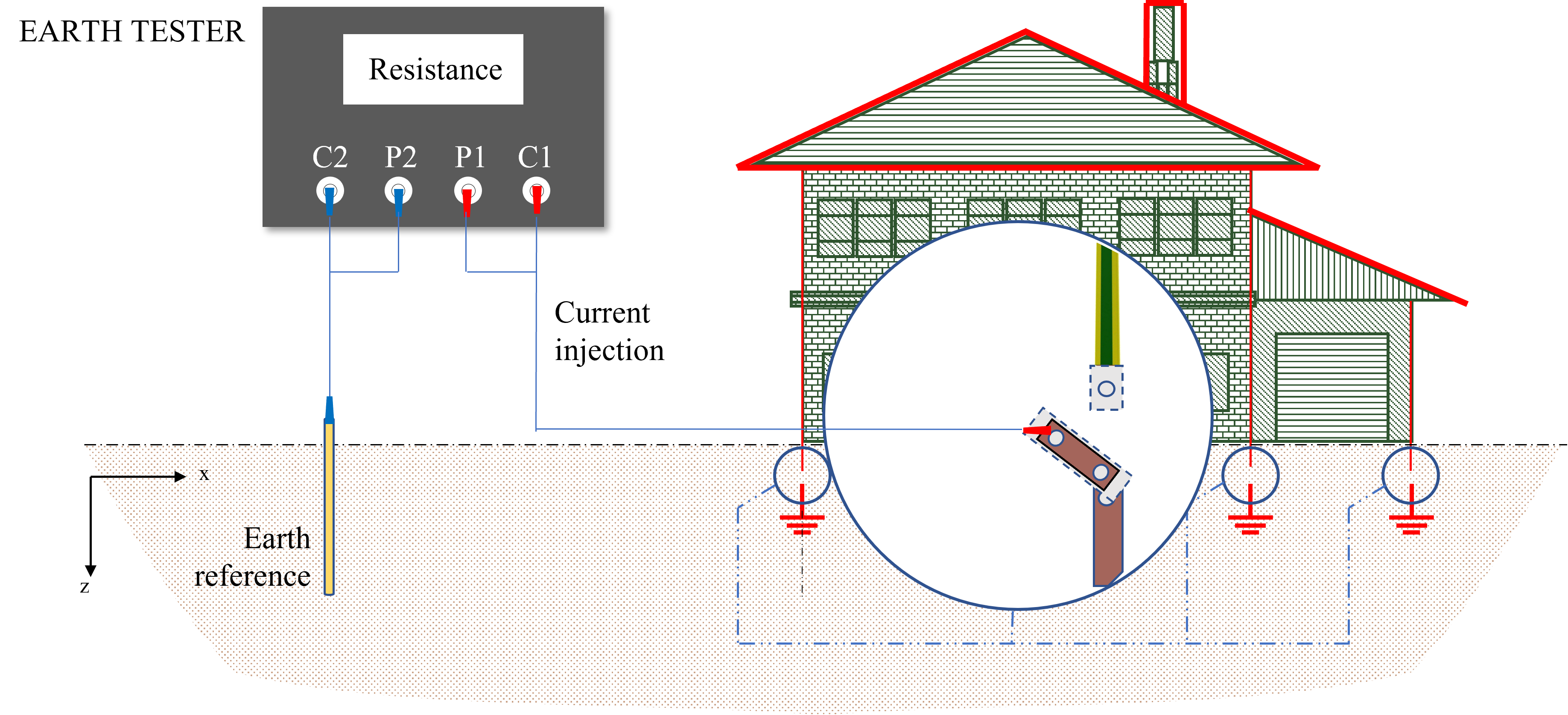
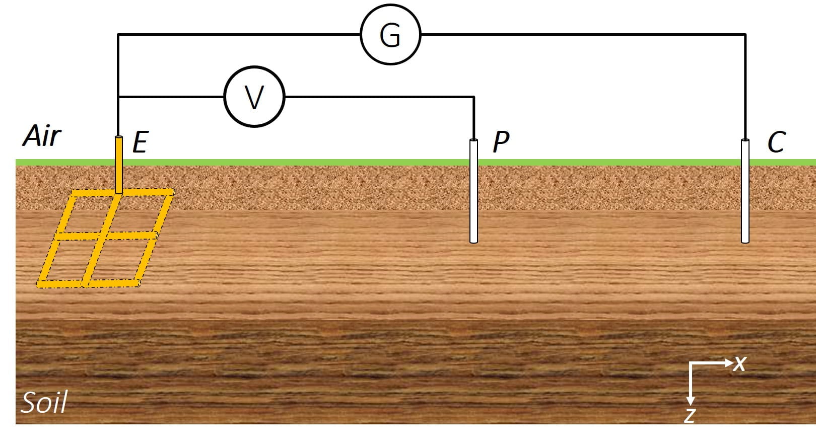
There are several methods to measure the earthing resistance, but the most common is that of the “3- pin”. This measurement uses 3 stakes that are connected to the measuring device as follows:
- •The first is the earth stake (or the connection to the loop at the bottom of the excavation),
- •The other two stakes are supplied with the tellurometer for the injection and measurement.
This measurement is made with a device called tellurometer where there is an injection of current into the earth at a constant voltage. Therefore, depending on the current measurement made by the device, it is possible to deduce the value of the resistance of the earth electrode. More details about the measurement can be found in [2,3].
The MEGGER DET 2/2 instrument, is designed to measure the earthing resistance and soil resistivity.
Once the measurement has been made, it is necessary to shift the stake “P” by +10% and -10% of the total distance, and repeat the measurement. If this measurement does not vary a lot, the measured value is accepted, and an average value should be accounted.
Fault current flow will first be through the contact resistors of the earth electrode. There is therefore around each earth electrode, crossed by a current, an area of influence whose shape and extent are unknown. From the limit of this zone, whatever the fault current, the potential is zero as shown in Fig. 6. During the measurements, it will be necessary to take care to plant the auxiliary socket “P” , also called “0V potential socket“ , outside the areas of influence of the auxiliary sockets through which the measurement current passes. This measure ensures a good result of the earth resistance measurement.
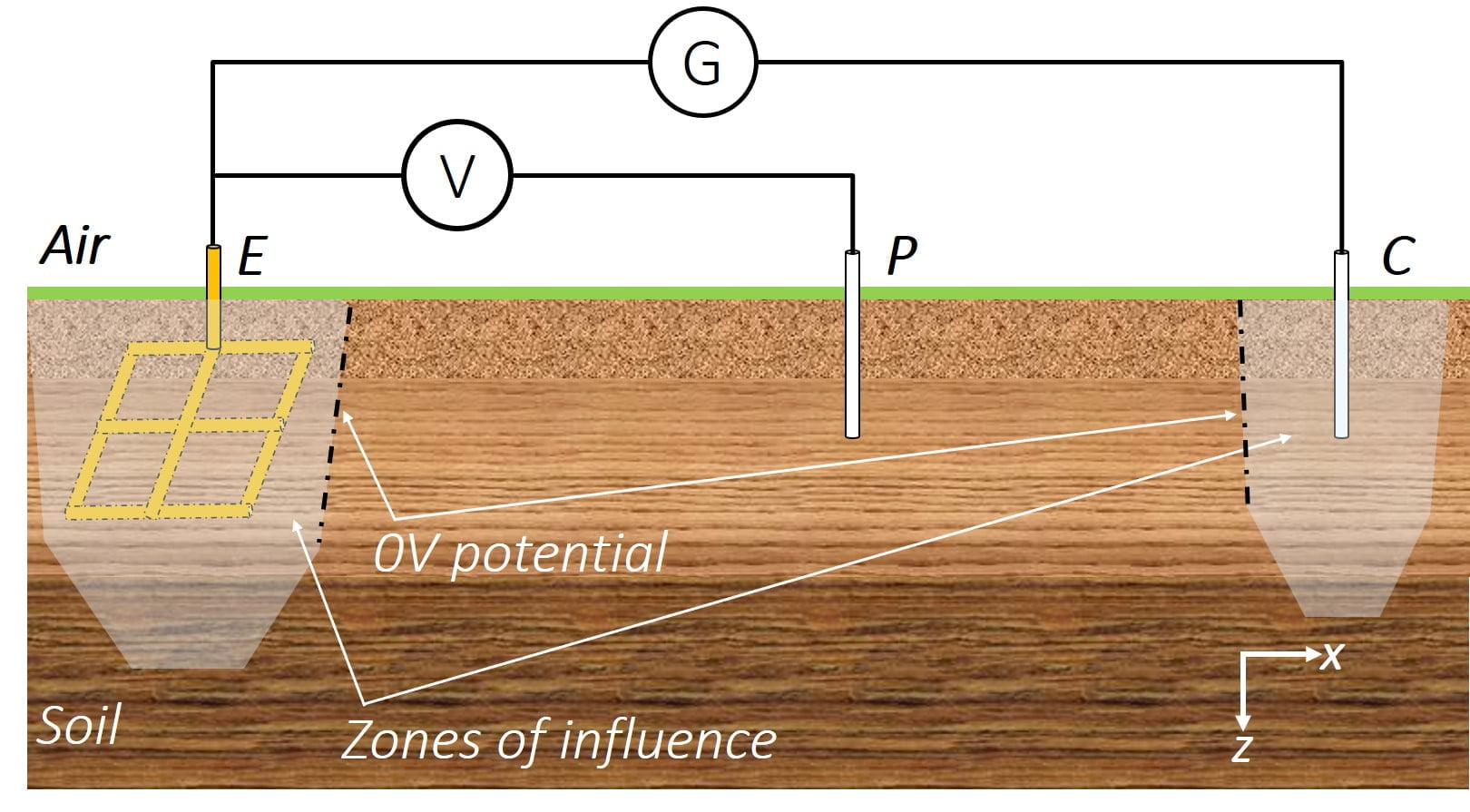
In general, the greater the distance between the earth stake “E” and the measuring stake “C” , the better the measurement of the resistance of the earthing system.
It should be noted that the same experimental setup is used to measure the earthing impedance for different current frequencies. One can use a variable frequency impedance measurement system or an RF system.
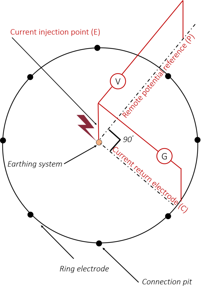
The experimental setup consists of an impulse voltage generator used to generate an impulse current of adjustable waveform and magnitude. A current injection wire connects the impulse generator to the system under test, suspended from wooden poles. Earth potential rise (EPR or GPR) is measured using a capacitive divider with reference to a remote potential imported via a second wire. The remote potential reference may be disposed orthogonal to the current injection path so as to minimise any electromagnetic coupling in the circuit. The current is measured using a current transformer.
In practical cases, the measurement setup is characterised by its proper power supply source as well as an isolation transformer.
Under transient and impulse currents, the performance of earthing systems is evaluated by the transient and impulse impedances. The transient impedance is the ratio of the measured voltage over the injected current. This impedance is characterised by a rapid decrease (describing the behavior of the electrode at high frequencies) before tending towards a constant plateau (corresponding to the resistance of low frequencies) .
Various impedance parameters at specific times have been also defined in the literature. These impulse impedances can be computed from the records of the measured voltage and the applied current. Fig. 8 shows an example, representing typical waveforms of the voltage and current.
The impulse impedance Z1, defined by the peakto-peak, is widely used to analyse the transient
performance of earthing systems. It is given by:
The Z2 is defined by voltage-current ratio
occurring at the current peak instant:

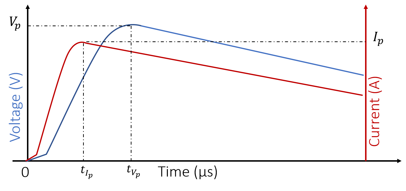
Finally, Z3 is represented by the ratio of the voltage and current values occurring at the instant of the potential peak:

These impedances permit to estimate the rise in the earth surface potential and the behaviour of the earthing system.
[1] IEEE Std 80-2013, IEEE Guide for Safety in AC Substation Grounding.
[2] IEEE Std 81 Guide for measuring earth resistivity, ground impedance, and earth surface potentials of a ground system.
[3] H115 (1984), Principes de conception et de réalisation des mises à la terre, EDF GDF.