Within electrical substations, a distance should be maintained between any energised conductor and any other part of the substation, including the earth. The minimum distance, known as a “safety distance”, is calculated with regards to the characterisation of the substation components and other factors that consider the operator’s movement across the site.
The earth grid design is influenced by many other parameters and factors such as the characterisation of fault sources and soil electrical parameters. From a safety aspect, designing a safe protective earthing system is essential in order to provide the shortest path for the effective flow of fault currents without exceeding the set operations and equipment limits.
In this light, national and international standards, as well as local regulations have been developed to identify the requirements of the earth grid design and define the relevant parameters for structures, electrical equipment, and systems therein. Figure 2 shows a simplified flowchart from the IEEE Std 80. This chart groups the design procedure into four main stages.
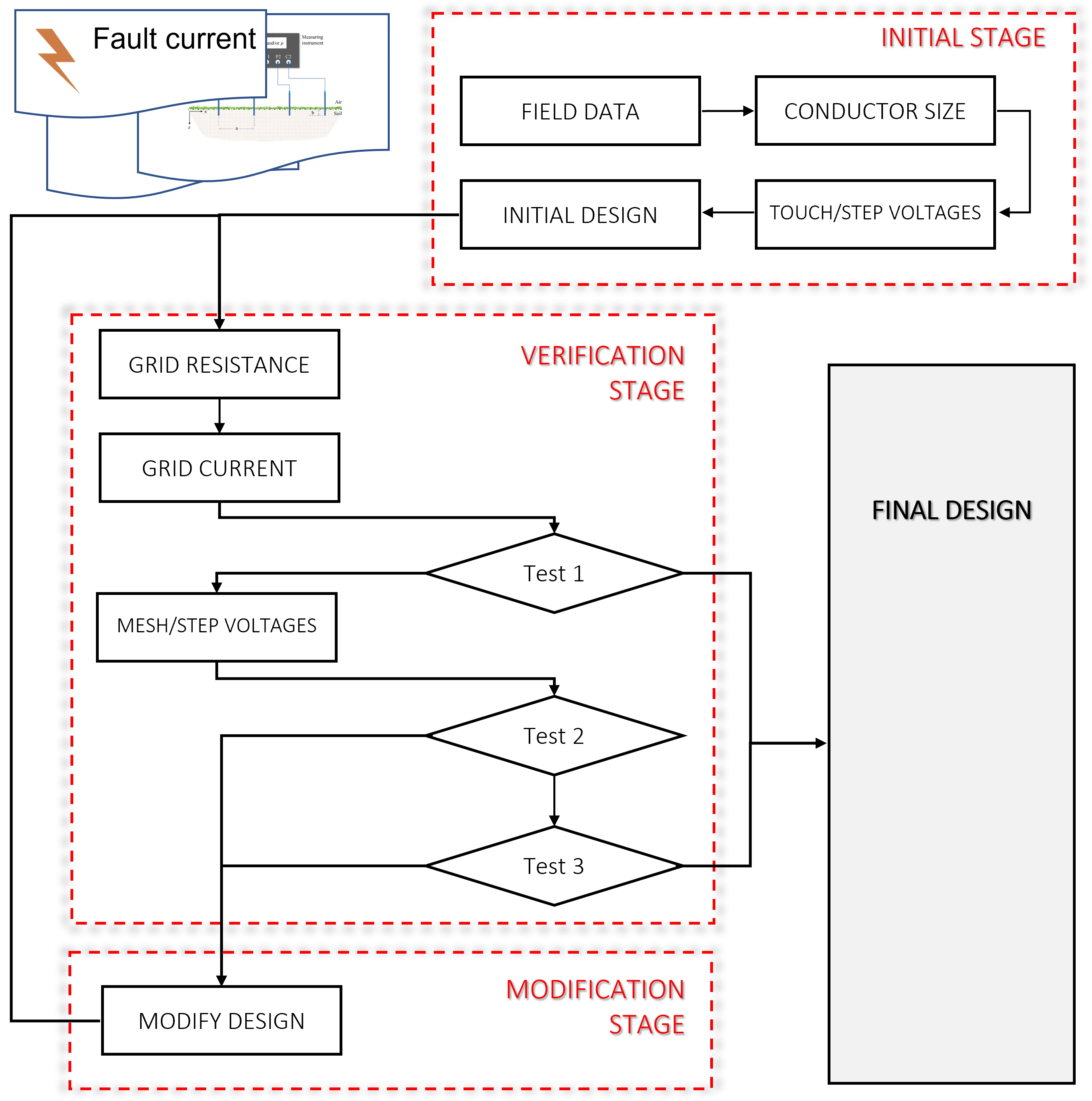
In the first stage, details of the project are essential. For instance, the general location plan of the substation should provide good estimates of the area to be covered by the earth grid.
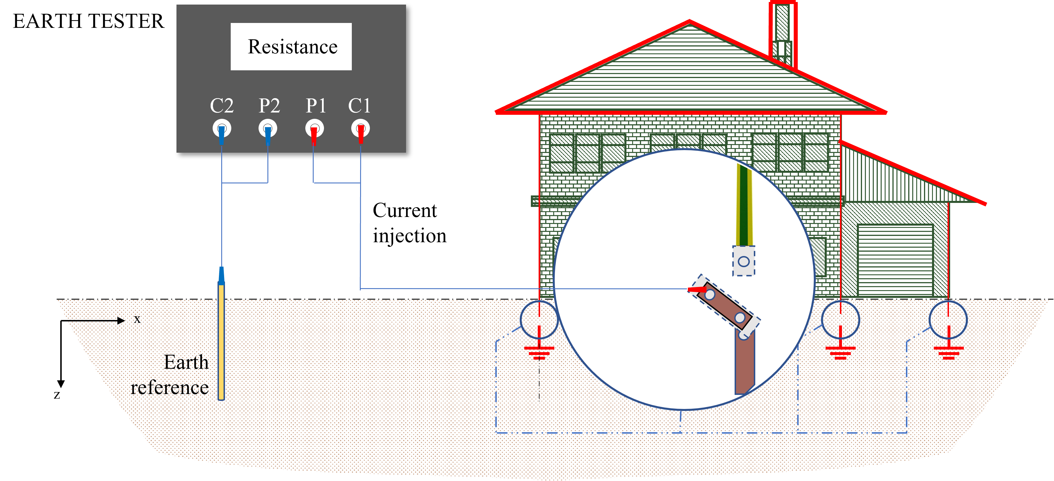
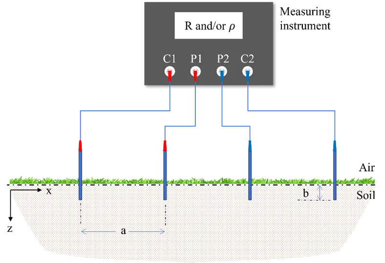
Multiple visits to the substation site are required to conduct the soil resistivity measurements. A series of measurements should be established using the four-pin method as represented in Figure 3.
In each measurement, the distance between electrodes is changed for vertical depth in the soil, while changing the horizontal position helps to check the change across the site. This process helps determine the soil structure as well as estimate an equivalent model of the soil resistivity.
A uniform soil resistivity model is the simplest representation that can be considered, which provides a single value of soil resistivity. However, this is not the representative of real life. For more accurate interpretation of soil resistivity measurements, other models can be used, namely: 1D multi-layer, 2D and 3D models.
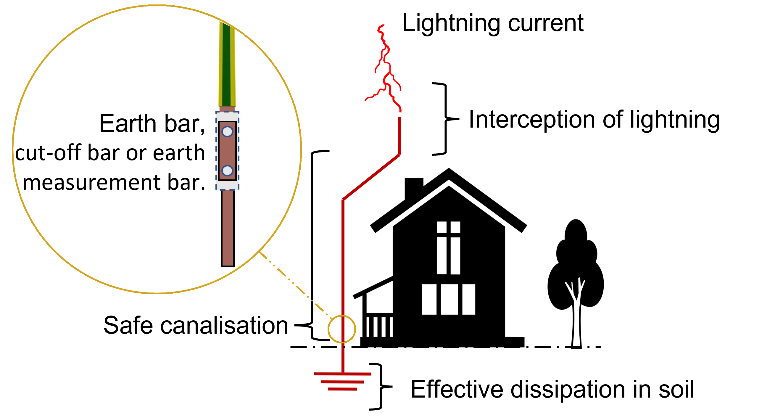
Corrosion (of different types) is one of the most important aspects that must be considered in the design of an earth grid. It can damage both the earthing conductors (conductor cross section) and the connection accessories. Consequently, fault and/or lightning currents cannot be dissipated effectively into the soil, adversity affecting the safety of people and the system operation.
For this reason, the conductor material should be selected so that soil conditions are not corrosive, maintaining the integrity of the earthing system for years (if the conductors are of adequate size). The shape of the conductor can be cylindrical, plate or a combination of both types as shown in Figure 4.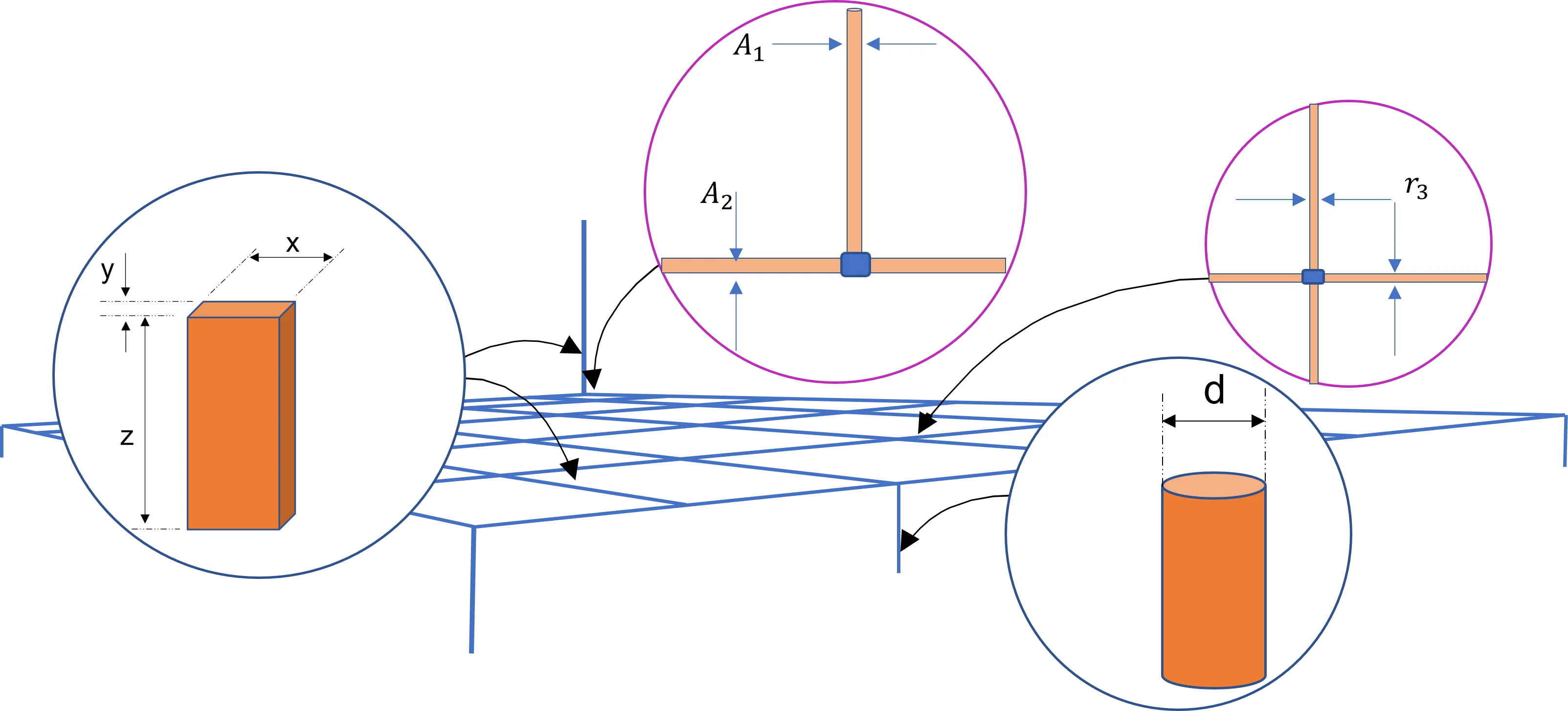
Earthing conductors should be also able to conduct the maximum fault currents during the occurrence of the faults (clearing time and backup). Various factors are included in the sizing of conductors such as the material thermal properties, current capacity, and impedance as well as the soil characterisation.
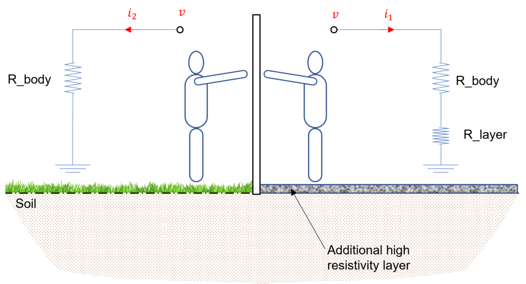
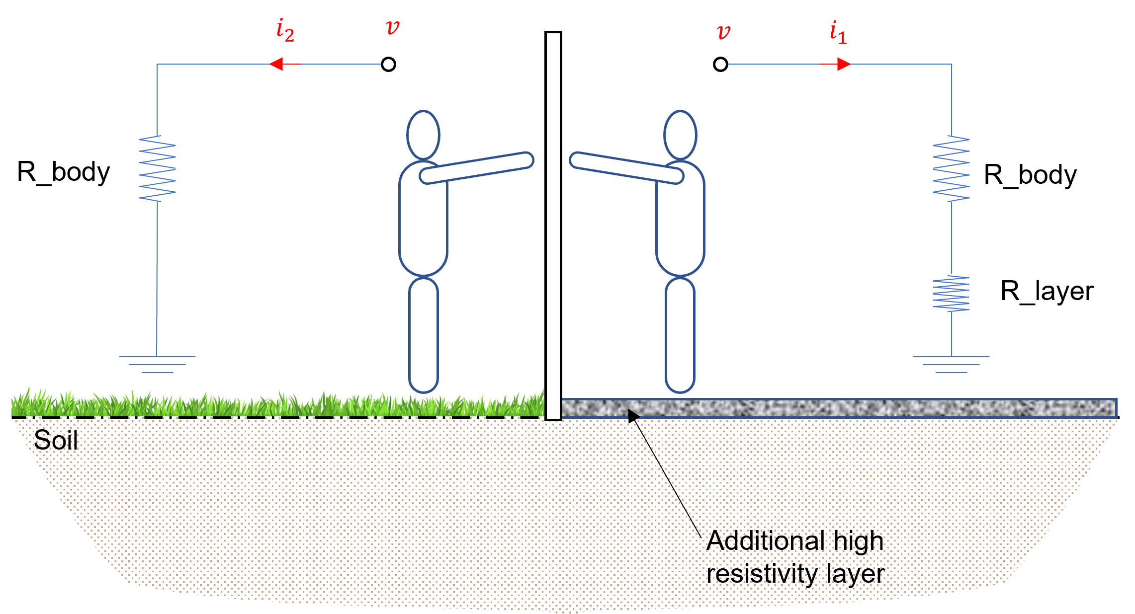
The next phase of the initial stage consists in determining the touch and step criteria. The maximum driving voltage of any accidental circuit should not exceed the limits defined by IEEE Std 80. The tolerable touch and step voltages are determined according to the characterisation of the surface material and the maximum expected fault current (magnitude and duration).
Usually, a protective surface layer of high resistivity (e.g., gravel) is used (as represented in Figure 5), to minimise the current passing through the human body, providing a safety to individual inside the substation.
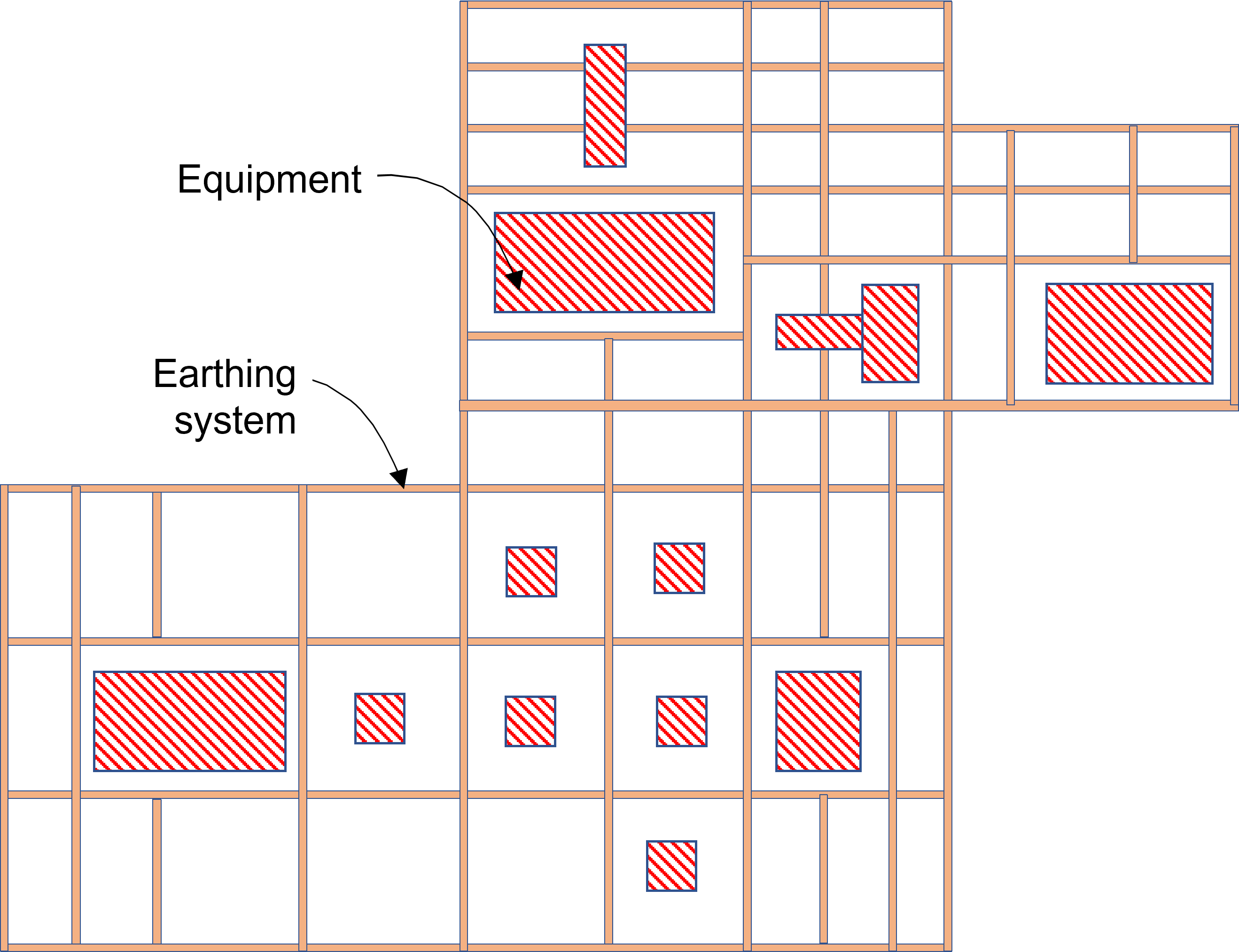
At this stage a preliminary design can be determined. According to IEEE Std 80, this design should include a conductor loop surrounding the entire grounded area, plus adequate cross-conductors to provide convenient access for equipment grounds, etc.
It is worth noting that the conductor spacing distance and earth rod positions can be estimated in accordance with the fault current in the substation.
The verification stage basically consists of controlling the safety measures within the substation. For example, Earth Potential Rise (EPR), also known as GPR, should be below the tolerable touch voltage computed in the initial stage. If this condition is verified, no further analysis is necessary at this level. In most cases, additional conductors are required in specific locations to bring voltages below tolerable limits. The design should also be rectified if the computed touch and step voltages are higher than the tolerable voltages.
Resistance to earth of the grid as well as the mesh and step voltages of the preliminary design can be estimated using a uniform soil model. However, more accurate estimates can be made by using computer tools and considering different aspects (e.g., frequency of the electric current). Analysis based on modelling the components of the earthing system and a multi-layer soil resistivity profile can determine the outcome with high precision.
The earth grid design can be reviewed many times before delivering the final version. In principle, these revisions aim to meet all the requirements and regulations for general safety of individuals and installations. A revision of the grid design is required when either the step or touch tolerable limits are exceeded.
According to the IEEE Std 80, the earthing design should be reviewed to eliminate hazards due to transferred potential and hazards associated with special areas of concern such as Communication circuits, rails, piping, fences and so on.
The final stage comes after fulfilling the requirements for the step and touch voltages. It consists in the enhancement of the earthing system through additional grid/rods in selected locations (e.g., rods in the earth grid corners). Additional rods can be driven in the area near the base of surge arresters and transformer neutrals (if applicable). Further earth grids/horizontal conductors may be required if the main earthing system does not include certain parts of the substation.
For any further questions, please don’t hesitate to reach out to us at [email protected]. Or contact us through our website to submit a query.
[1] IEEE Std 367:2012, IEEE Recommended Practice for Determining the Electric Power Station Ground Potential Rise and Induced Voltage from a Power Fault.
[2] IEEE Std 80:2013, IEEE Guide for Safety in AC Substation Grounding.
[3] IEEE Std 81:2012, IEEE Guide for measuring earth resistivity, ground impedance, and earth surface potentials of a ground system.
[4] Zhang et al., “Research Advances of Soil Corrosion of Grounding Grids”, Micromachines 2021, 12, 513. DOI: 10.3390/mi12050513.