Lightning is mostly a consequence of the development of a convective weather system to a certain magnitude, with strong links to the development of discharge processes within the system. As we saw in our previous blog piece, an air volume can be uplifted in an unstable convective condition, taking part in the development of cumulonimbus. This process is accompanied by strong frictions between the air molecules, induced by the updrafts and downdrafts under the action of thermodynamic and/or topographic conditions. This process, along with others related to the displacement (at different speeds) of various phase states of hydrometeors, is accompanied by electron transfers, phase state changes and electric charges separating into different charge regions responsible for producing lightning. Therefore, lightning can be considered as an indicator of the onset and course of severe convection.
Our understanding of lightning is actually based on numerous direct and indirect observations. Direct measurements are performed at lightning research stations located around the world and actively working on collecting the data of lightning discharges. Indirect methods rely on the empirical relation between the lightning channel current and electromagnetic field measured at some distance from the lightning discharge. Smorgonskii et al. [1] presented an interesting work that provides a number of reports on extreme lightning parameters such as peak current, fastest and slowest rise time, fastest and slowest time to half value, rate of change of current, flash duration, charge and action integral. They categorized lightning discharges as a function of their origin and direction of propagation as shown in Fig. 1.
![Classification of lightning discharges, reproduced from reference [1]](https://kingsmillindustries.com/wp-content/uploads/2021/08/Classification-of-lightning-discharges-reproduced-from-reference-1.jpg.webp)
Referring to [3], lightning, or the lightning electrical discharge, in its entirety is usually termed a “lightning flash” or just a “flash”, whether it strikes the earth or not. In addition, the term “lightning strike” generally corresponds to a lightning discharge that involves an object on the earth or the earth surface. It should be noted that the terms “stroke” or “component stroke” relate only to components of cloud-to-earth discharges. Moreover, we can also find some other commonly used non-technical terms for lightning discharge such as “lightning bolt”.
Understanding the lightning discharge and its characteristics is an important task because the probability of lightning damage depends on the lightning current characteristics among many others (e.g., structure, connected lines, efficiency of applied protection measures etc.).
Indeed, lightning discharge is a transient phenomenon that can be considered to be an almost ideal current source since it is a load-independent current. Fig. 2 shows a typical representation of the first lightning stroke current waveform.
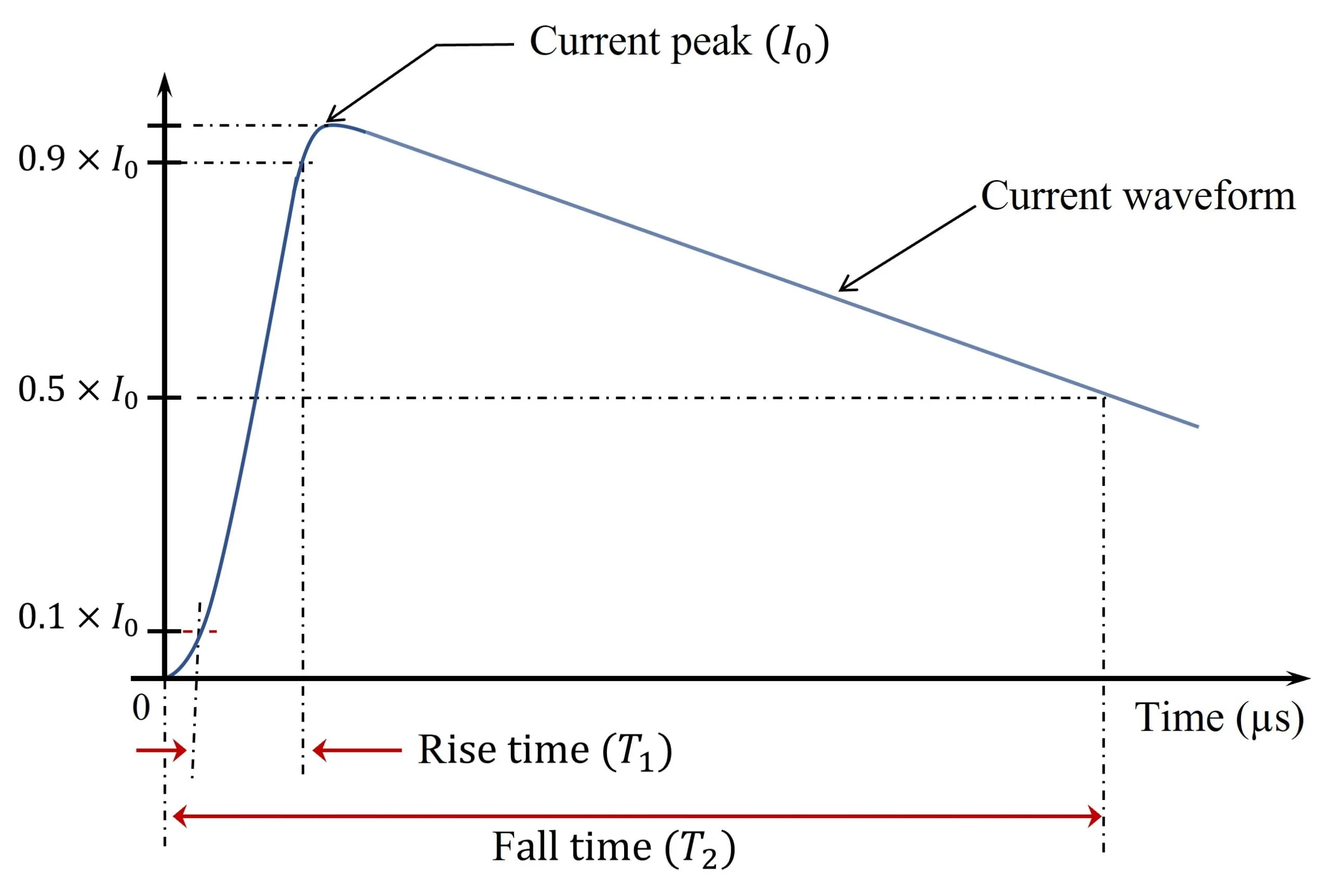
It is well known that lightning parameters are required for various engineering applications. Among these parameters, emphasis should be placed on those that have a considerable influence on the engineering calculations of electrical power, and those necessary for the design of lightning protection and earthing systems. Figure 2 defines the main three key parameters of lightning discharge according to the international standard (e.g., [4],[5]). These parameters are the current peak and the two time constants necessary to define the current waveform. In order to design protective circuits to reduce the potentially harmful effects of lightning transients, one needs to know the expected waveforms and maximum signal amplitudes of the transients. In fact, other parameters should be considered, along with the above, in the case of lightning protection related studies, such as the charge, the discharge duration, the specific energy and the rate of rise of the impulse current [4].
As stated in [6], direct current measurements were obtained over a period of more than 20 years by Berger et al. [7]. For this, the most complete characterization of the lightning return stroke can be found in their works, which are based on oscillograms of current measured using resistive shunts installed at the tops of two 70-m high towers on the summit of a 915-m high mountain (above sea level).
It is worth noting that the parameters of lightning return-stroke currents are of great importance in studying lightning protection systems as well as the surge protection of electrical power and communication systems. These key parameters of lightning current help to determine the type and severity of damages.
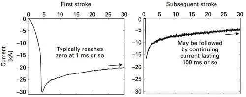
The current peak value represents a very important parameter since it governs the severity of the lightning current waveform. As indicated in Fig. 2, it corresponds to the maximum value of the lightning current. In lightning protection studies, numerical values relevant to the first lightning stroke current should be considered [4]. This is because the first lightning stroke is characterised by a current peak higher than that of subsequent lightning strokes. Figure 3 illustrates curves of typical current waveforms of negative lightning first and subsequent return strokes.
The electrical parameters of lightning depend on multiple factors such as the location of the lightning strokes. In this light, and based on various techniques and tools to detect lightning, it has been possible to map the annual lightning flash rate with some associated statistics.
In fact, the distribution of lightning around the world is far from a uniform distribution. At extreme values, it is found that the largest peak currents inferred from measured fields ever reported are −957 kA for negative and +580 kA for positive flashes [9]. Commenting on these values, the authors [1] stated that the remote estimations are based on the assumption that the observed relationship between the peak electric/magnetic field and the peak return stroke current measured in triggered subsequent return strokes is valid also for first return strokes and that it can be extrapolated to larger currents. They also mentioned the fact that the estimation of the peak value is dependent on an unknown parameter for specific strokes – the speed of the return stroke. Other values of the current peak can also be found in literature, which are in the range of a few hundreds of kilo-amperes. For instance, a peak value of about 340 kA (respectively 200 kA) was measured directly for a negative (respectively positive) flash [1].
It is clear that lightning strokes include a certain number of subsequent lightning strokes, generally between 3 and 5, associated with the constructed fully conductive lightning channel. Therefore, the steepness of the lightning current of the first stroke is not as steep as that of the next short stroke as can be deduced from Fig. 3. For this fact, the steepness of the subsequent lightning strike is usually considered for assessing the highest induced voltage in a given conductive loop. Figure 4 shows an example (associated to Fig. 3) of the typical evolution of the rate of change for current waveforms of a negative lightning first and subsequent return strokes.
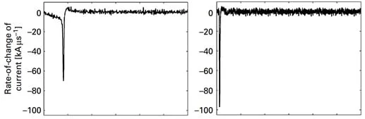
Overvoltages and other dangerous sparking produced by inductive coupling are mainly related to the average steepness (di/dt) of the lightning current front. These voltages are induced in all open and/or closed conductor loops located in the vicinity of conductors through which lightning current is flowing. As a key parameter, the maximum rate of rise (called, current maximum steepness) of the lightning current during front time should be considered.
Rise time to peak, or just rise time, refers to the time it takes for the leading edge of the lightning current to rise from its minimum to its maximum value. Rise time to peak is typically measured from 10% to 90% of the value as represented in Fig. 2. Conversely, the second time constant (fall time) represents the measurement of the time it takes for the pulse to move from the highest value to the lowest value. In our case, the half-peak time represents the time interval between the virtual origin O and the instant at which the current has decreased to half the peak value. Let T1 and T2 be the rise and fall time of a lightning impulse current, such a transient is called a T1/T2 µs waveform.
Several waveforms can be initiated depending on the anticipated application. The most common waveforms are the 8/20 µs (and 10/350 µs) current waveform and the 1.2/50 µs voltage waveform. They are mainly specified in standards for designing lightning protection of low-voltage power lines, high-voltage equipment on distribution and transmission lines [5, 8].
Authors in [1] have collected and organised data of the extreme reported values associated with lightning currents. They found that the fastest rise times correspond to an upward negative stroke while the slowest rising times correspond to a winter positive upward lightning in Japan. In addition, it is found that the shortest and longest half-peak intervals have been reported in a study from Japan in 1992 and correspond to an upward negative and positive strokes, respectively. Other extreme values are given in Table I.
![Extreme values of time constants (µs), reproduced from [1]](https://kingsmillindustries.com/wp-content/uploads/2021/08/Extreme-values-of-time-constants-µs-reproduced-from-1.png.webp)
The total duration of the flash represents an interesting parameter for engineering applications. It helps computing the total charge of a lightning transient, which is the time integral of the lightning current for the entire lightning flash duration. Extremely high values of charge are transferred from the cloud to a given object in the air or on the air surface. This transferred charge causes melting and erosion of several materials [10].
In addition, one can compute the action integral, which represents the specific energy of the lightning discharge. It is the integral of the current squared over time, usually used to define the thermal heating once the lightning current has entered a conductor (e.g., down conductor, downlead).
Other important parameters can be used for designing a lightning protection system, which are very different depending on the type of lightning discharge [11]. These parameters include the flash multiplicity, the channel impedance, lightning return-stroke speed ,and the sequence of current components.
For instance, the flash multiplicity is the number of return strokes in the flash. Typical time intervals between them are in the order of tens of µs. Moreover, the lightning return-stroke speed is needed in computing lightning electromagnetic fields that cause induced overvoltage in power distribution lines. The average propagation speed of a negative return stroke is typically ranging between one-third and one-half of the speed of light [11]. Furthermore, the equivalent impedance of the lightning channel is needed for specifying the source in studies of either direct strike or induced lightning effects. It is reported in [11] that the estimates of this impedance suggest values ranging from several hundred ohms to a few kiloohms.
[1] A. Smorgonskiy, M. Rubinstein and F. Rachidi-Haeri. Extreme Values of Lightning Parameters. 2018 International Lightning Detection Conference (ILDC), Fort Lauderdale, FL, USA, 2018.
[2] J. Jerauld et al., Insights into the ground attachment process of natural lightning gained from an unusual triggered-lightning stroke, Journal of Geophysical Research, 2007.
[3] Rakov VA. Lightning phenomenology and parameters important for lightning protection, 9th International Symposium on Lightning Protection, 2007.
[4] IEC Standard, IEC 62305, Protection against lightning, 2012.
[5] IEC Standard, IEC 61643, Low-voltage surge protective devices – Part 11: Surge protective devices connected to low-voltage power systems – Requirements and test methods, 2011.
[6] Hans D. Betz, U. Schumann and P. Laroche, Lightning: Principles, Instruments and Applications Review of Modern Lightning Research, Springer Science and Business Media B.V., 2009.
[7] K. Berger, R.B. Anderson, and H. Kroninger, Parameters of lightning flashes, Electra, 80:223–237, 1975.
[8] M.A. Uman, The Art and Science of Lightning Protection, Cambridge University Press, 2008.
[9] W. A. Lyons, M. Uliasz and T.E. Nelson, Large Peak Current Cloud-toGround Lightning Flashes during the Summer Months in the Contiguous United States, Monthly Weather Review, vol. 126, no. 8, pp. 2217–2233, 1998.
[10] A. Smorgonskiy et al., Are Standardized Lightning Current Waveforms Suitable for Aircraft and Wind Turbine Blades Made of Composite Materials?, IEEE Trans. EMC, vol. 59, no. 4, Aug. 2017.
[11] CIGRE. (2013). Lightning Parameters for Engineering Applications (Brochure No. TB 549).