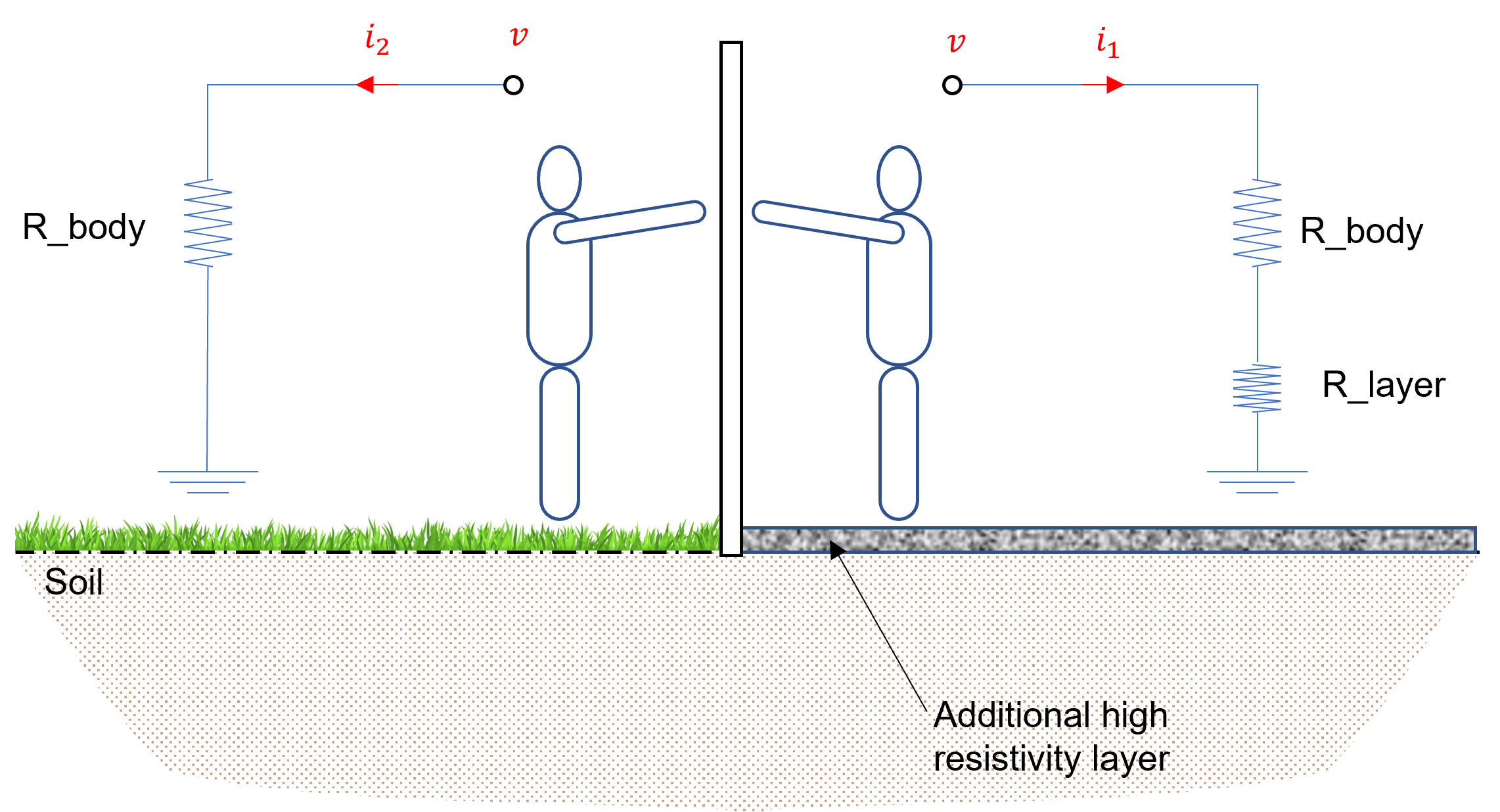
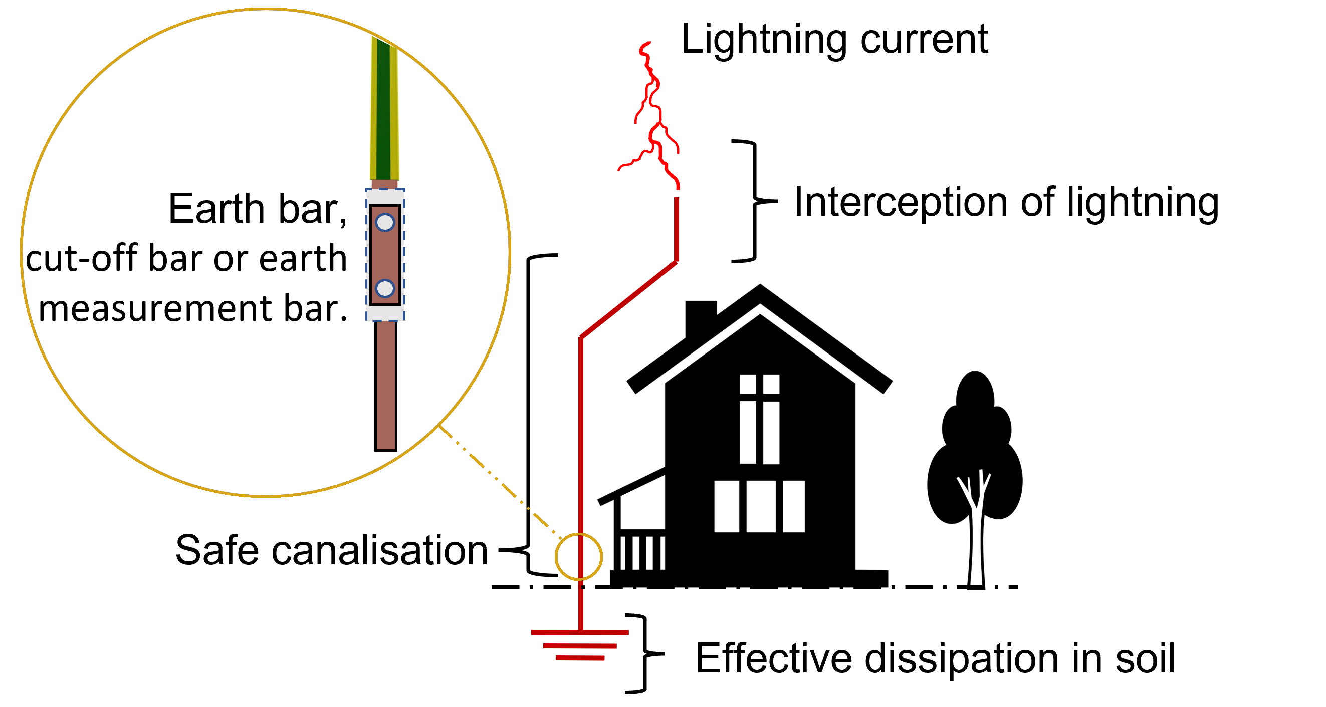
Faults can occur anywhere on the system but are most common on outdoor transmission lines. Such faults are usually characterised by extremely high currents. Although the power system can protect itself from such faults (e.g., using overcurrent or distance protection), there may be short periods where extremely high currents are present. These high currents can lead to dangerously high step and touch voltages which can lead to injury of nearby personnel. Providing a low impedance path to ground is a key mitigation measure to minimise such risks.
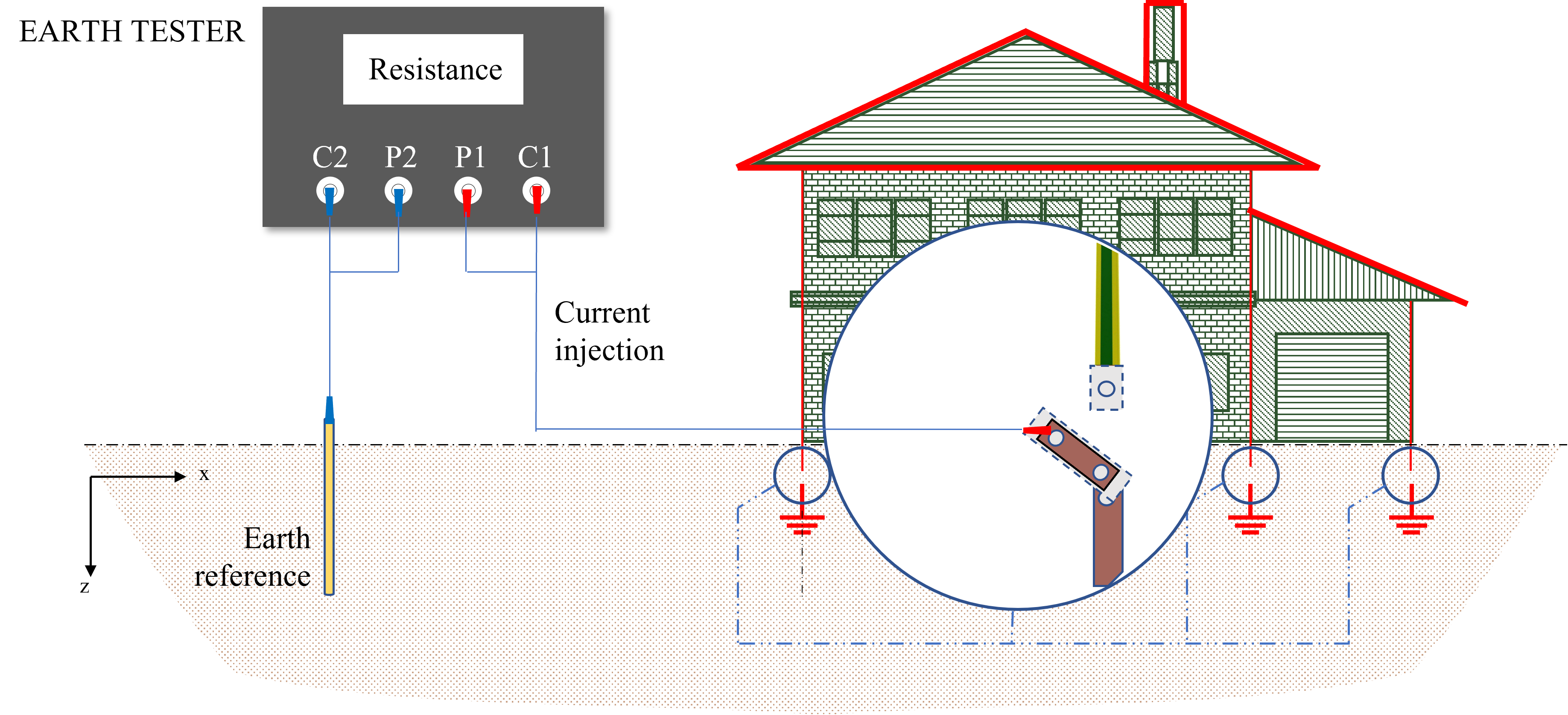
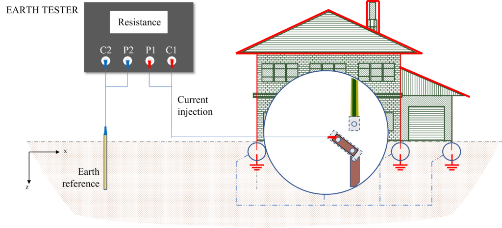
This figure illustrates a representation of an earth bar and shows its state during the measurement of the earthing resistance. It should be noted that several earth bars may exist in the same installation.
Quite simply, an earth bar is a strip of metallic conductor designed to be a common point to which all conductive components and services, such as water and gas pipes, power, telecommunications, and data cables should be connected.
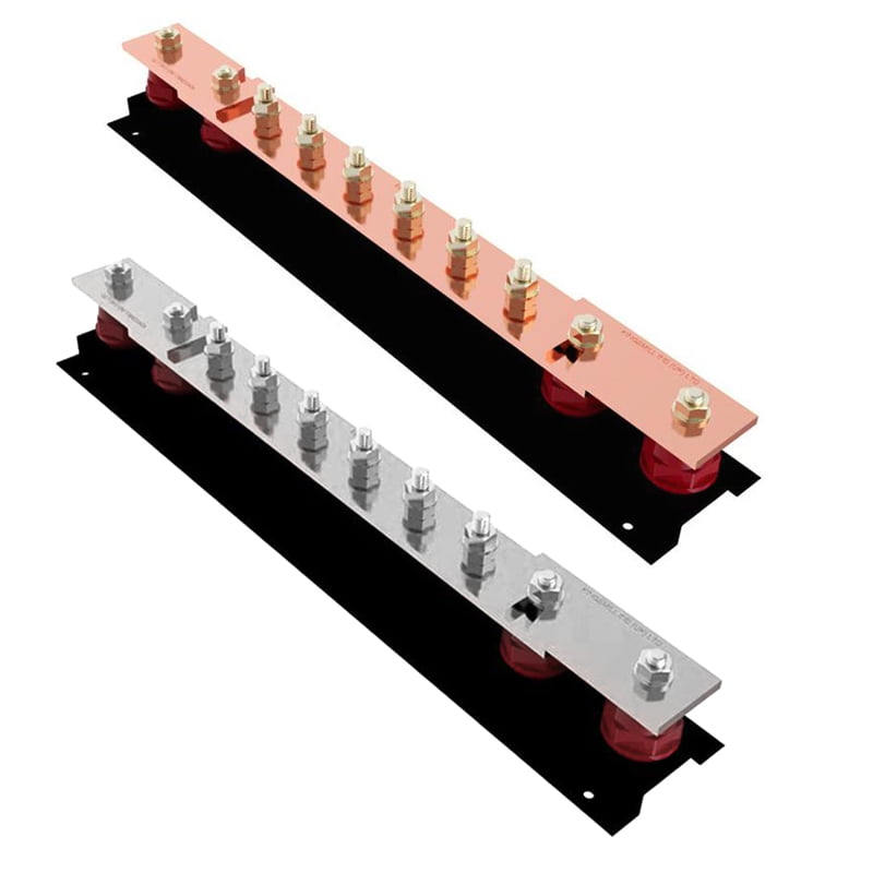
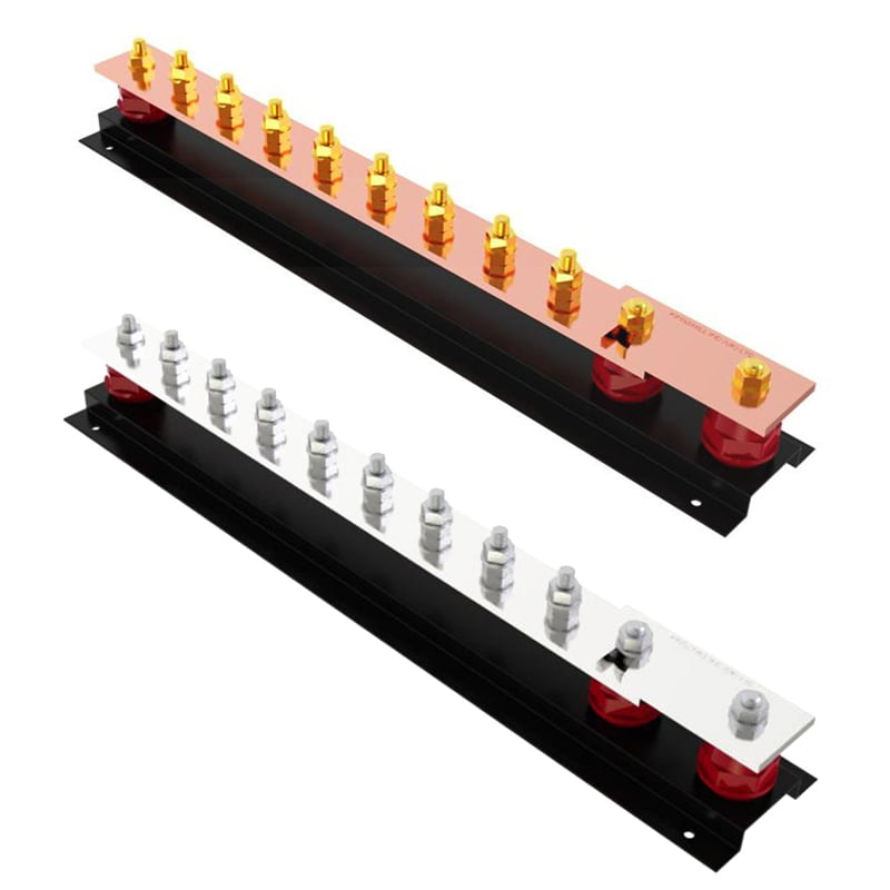
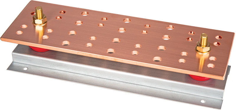
Standard earth bars are an efficient and convenient way of providing a common earth point. These bars are usually designed in accordance with a specific application. For instance, telecoms earth bars (right in Figure 2) differ than industrial/power earth bars.
The twin disconnecting links are mainly used to offer a temporary break in the connection to the earth, allowing the inspection and testing of multiple earth rods/systems while disconnecting them from the lightning protection and earthing system.
Earth bars must be adequately selected by considering various aspects. The first thing to mention is that an earth bar consists of materials used in earthing systems. Therefore, it must be able to provide a low impedance path to earth carry the maximum fault currents. In addition, it should resist corrosion and withstand mechanical damage.
A base made of GRP (Glass Reinforced Polyester) is usually used in earth bars to provide mounting and insulation from metallic surfaces. It also makes the earth bars easier to handle.
The careful selection of the material, cross-sectional area, and dimension some of the many factors that should be considered by experienced personnel in accordance with national and international standards. Thus, Kingsmill Industries have offered several designs to meet the requirements of the protective systems in any given installation.
All conductive components and services, such as water and gas pipes, power, telecommunications, and data cables should be connected to a single earth bonding bar (i.e., equipotential bonding). For this reason, every earth bar should be installed in a way to allow easy access for testing and inspection, as represented in Figure 3.
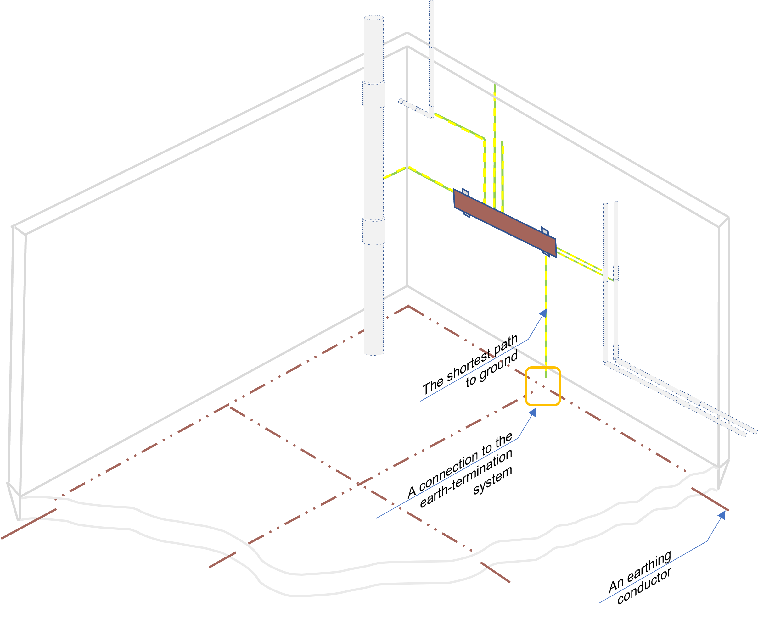
Earth bars should be installed in the basement or approximately at ground level where insulation requirements are not fulfilled. Each earth bar should be connected to the earthing system via the most direct route as represented in Figure 4.
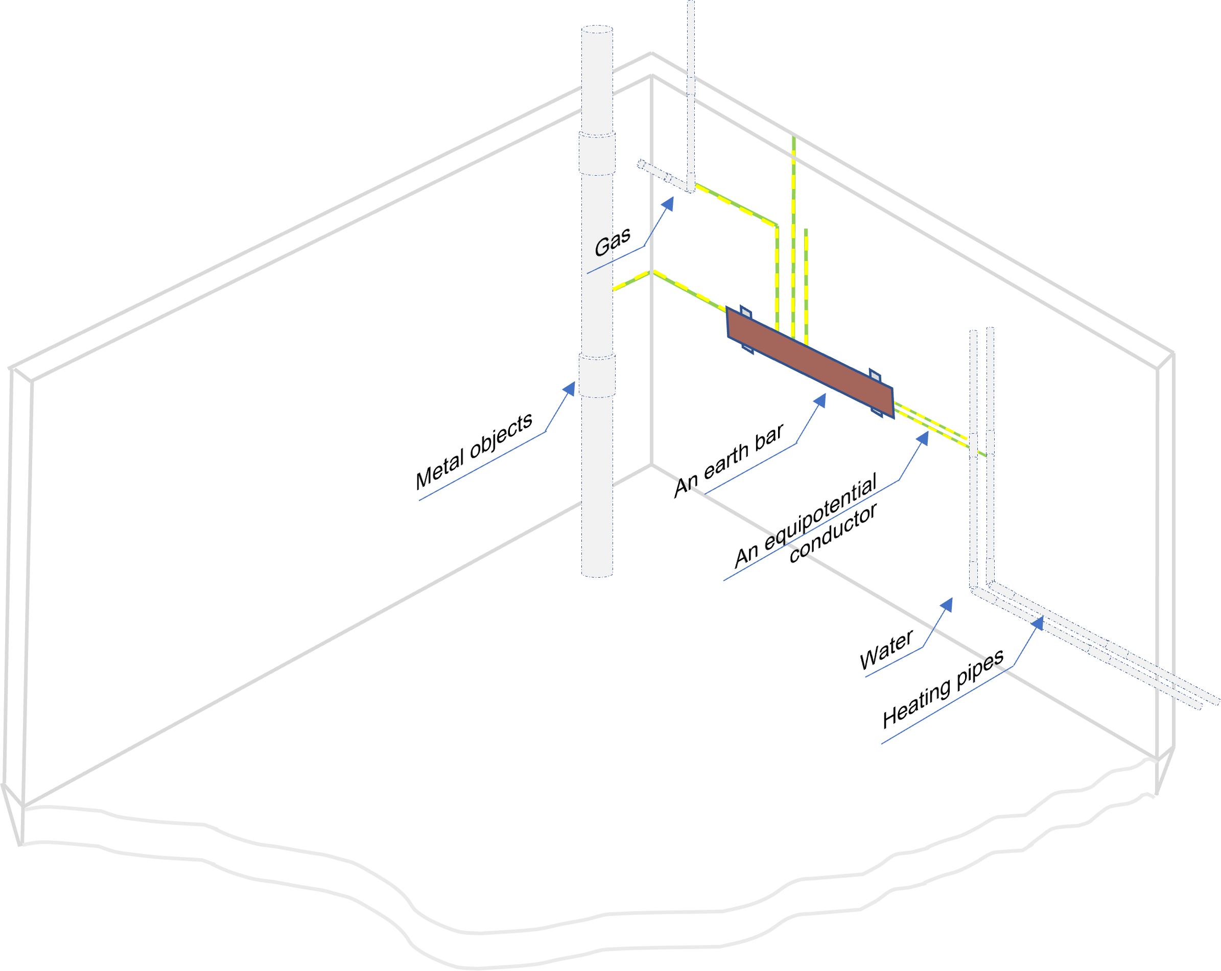
Regarding the location of the earth terminal bar (or, the main earth bar), a provision should be considered for future earth bar connection, remembering that it is also facilitating the interconnection between the actual system and any future installation.
It is good practice to make sure that every earth bar is above ground, installed as a bolted connection and is in a safe area to avoid corrosion. According to the BS EN 62305-3, however, an earth bar of an isolated external LPS should be installed at ground level only.
It should be noted that more than one earthing bar can be installed in the same structure. This is normally for large structures of more than 20 m in length as stated by the standard [BS 62305-3]. In this case, all earth bars should be interconnected, and a ring earth bar may be used.
[1] British Standard Publications, Code of practice for protective earthing of electrical installations, BS 7430.
[2] British Standard Publications, Requirements for Electrical Installations. IET Wiring Regulations, BS 7671.
[3] British Standard Publications, Protection against lightning Part 3: Physical damage to structures and life hazard, BS EN 62305.

