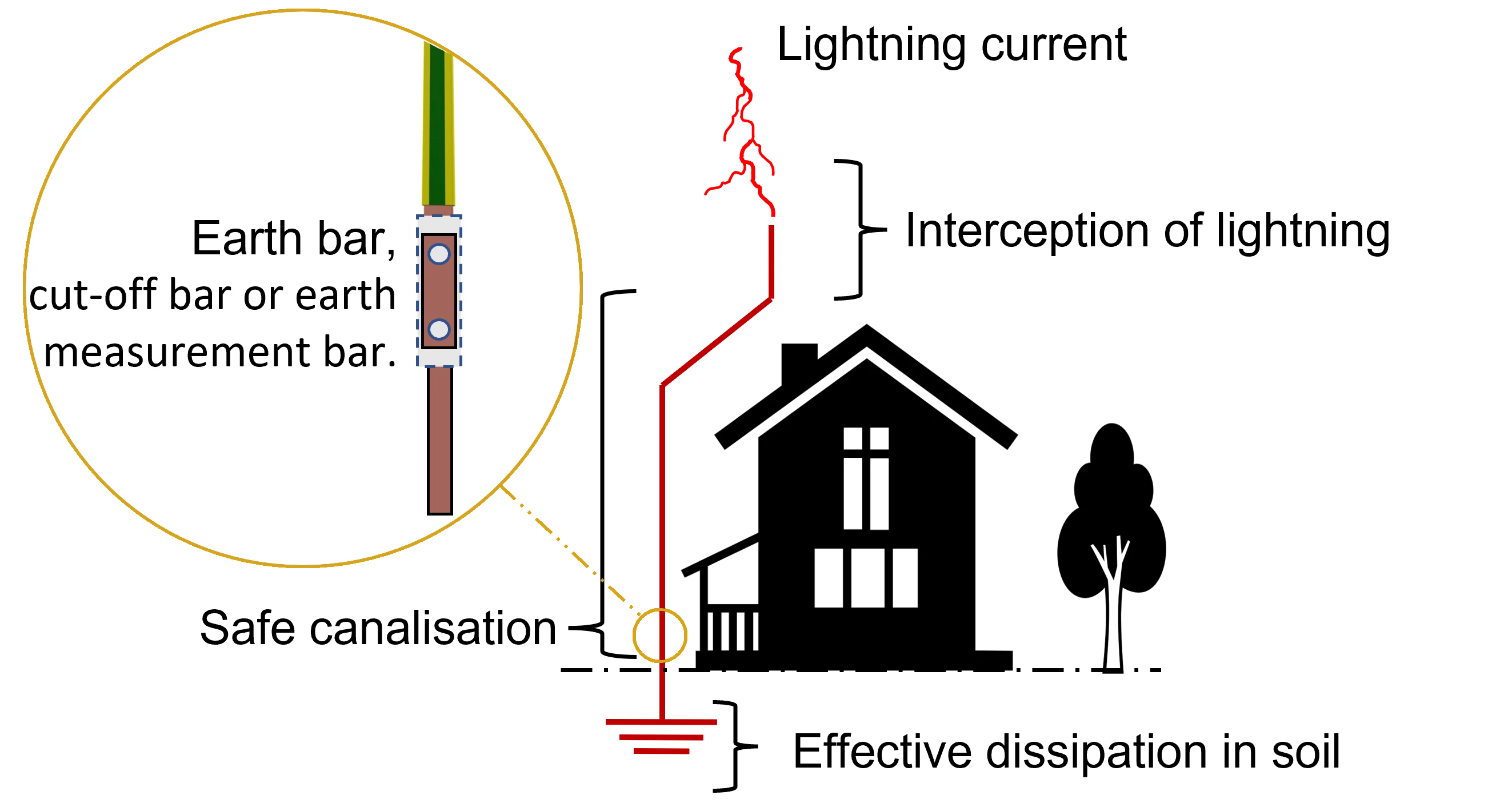
The purpose of an earth termination network or an “earthing system” is to provide a low impedance pathway for both electrical faults and lightning discharge currents to safely dissipate into the ground. At Kingsmill Industries, we stress the continuous and consistent operation of your earthing system. It is critical to ensure the safety of the electrical installation, building occupants and electronic items contained within. An earthing network with weak links in its chain can compromise the entire system creating costly and potentially lethal situations.

It is not only important that your earthing system is properly designed to handle the maximum fault current, but that the system itself is constructed from high quality components that will resist corrosion and degradation over time. The British Standard BS 7430 provides guidance on the design and installation of earthing systems, along with material specifications regarding the quality of its components.
While oftentimes, much attention is given to proper design, it is equally, if not more important to select quality materials that meet the application needs of the building. This will go a long way towards ensuring the system lasts and provides continuous and safe pathways for both electrical faults and lightning discharge currents. Various materials are available, providing a range of solutions to cater to the needs of the earthing installation. In our discussion below, we will examine the different components that make up an earthing system and what to keep in mind when making a product selection. For more information download the Kingsmill catalogue or speak with one of our specialists by submitting a query on the website.
The materials that make up an earthing system can be divided into seven categories:
- Earth Bars
- Earthing Conductors
- Earth Electrodes
- Inspection Pits
- Soil Enhancers
- Connecting Clamps
- Earth Rod Seals
Let’s take a closer look at each one.
Purpose: Earth bars serve as a common point (or main earthing terminal) for the earth continuity and equipotential bonding conductors to be grouped together for onward connection to the external earthing system.
Earth bars are typically located in control rooms and can be fitted with disconnecting links for convenient system testing.
Earth bars must be designed to handle the maximum potential fault currents that the structure will encounter. At Kingsmill Industries, our earth bars have been tested to BS EN 62561-1 Connection Components.
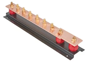
When selecting an earth bar, it is important to have the following information at hand:
- How many conductors will connect to this earth bar? This will determine the number of ways you need for your earth bar.
- Do you require a disconnecting link for testing the system? A disconnecting link allows you to test the earth continuity from the bar without having to remove the connections.
- If you do require a disconnecting link, do you want to get an outgoing way? An outgoing way enables the connection to earth to be isolated from the test link, thus allowing the test link to operate without the need to loosen or disconnect the direct earth connection on the earth bar.
- What size lugs are you connecting to the bar? Standard earth bars typically have 35mm spacing between fixings, allowing for up to two 185mm2 cable lugs to be connected adjacent to each other. Larger lugs will require more spacing to allow for proper connections. Additionally, are you using lugs with one or two holes in the palm?
- Where will you be putting your earth bar? If outdoors or in a humid area, you may want to consider tinning for your earth bar along with a hot dipped galvanized base to inhibit corrosion.
Purpose: Earthing conductors are used to connect the structures’ earthing terminal (i.e. the earth bar)
to the earthing electrode in your inspection pit.
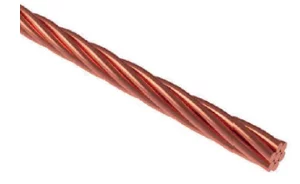
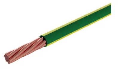
What to Keep in Mind: There are various types of earthing options available depending on your site’s particular needs and ground conditions. The main 4 types of earthing electrodes are:
- Solid copper earth plates
- Copper lattice mats
- Solid or copper bonded earth rods
- Copper conductor in the form of tape of cable
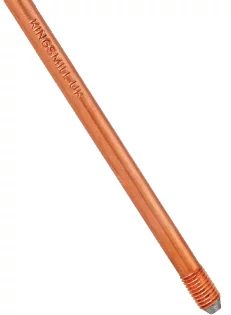

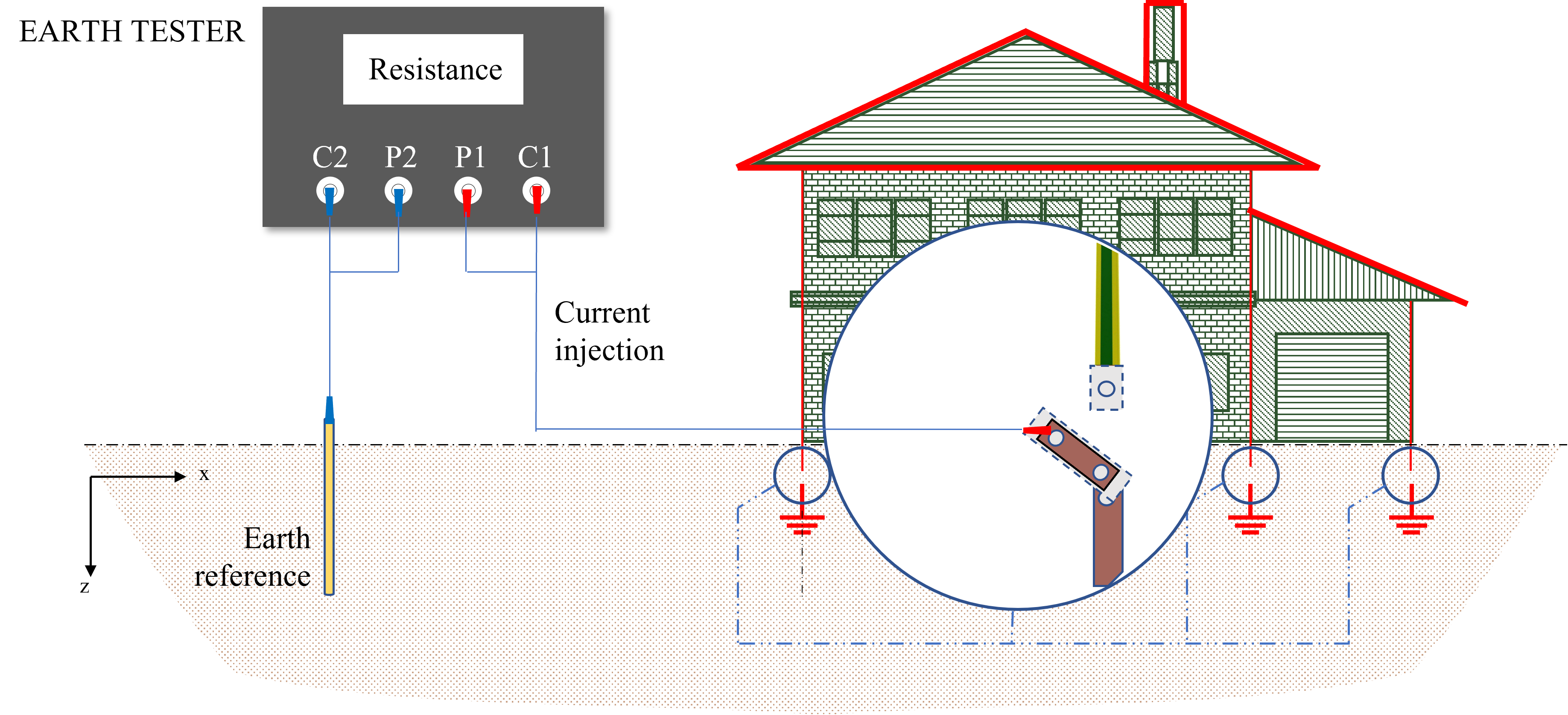
When installing your earth electrode, the objective is to achieve a low resistance for your earthing system to attract fault currents and an overvoltage towards the lower potential. Sometimes, the ground into which you are installing your earth electrode has poor conductivity (high resistance), or in other cases, your space is limited and you need to reduce the resistance of an area even further to avoid digging deeper or wider holes/trenches. That is where soil enhancers come into play by effectively lowering the resistance of the soil.
Purpose: Soil enhancers are used as backfill in holes and trenches to lower resistance (increase conductivity) of the soil surrounding the earth electrode. What they do is effectively increase the surface area of the metal electrode by encasing it in a highly conductive medium. This increased surface contact helps to improve dissipation.
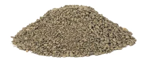

What to Keep in Mind: While some contractors may opt to use salt and charcoal, there are two more prevalent methods that require less frequent maintenance.
Bentonite is a moisture retaining clay that swells to several times its dry volume when combined with water. Bentonite will hold moisture for some time and can also absorb water from rain. The retained moisture increases conductivity it relies on the presence of permanent moisture or rainfall to be effective.
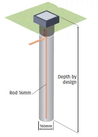
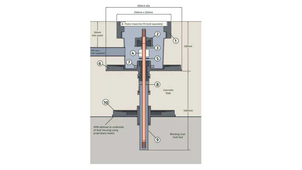
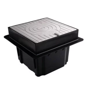
Purpose: Inspection pits, house the connection point between your earthing conductor and the earth electrode. They serve as a test point for your earth electrode/system.
What to Keep in Mind: Inspection pits come in different sizes and types based on your requirements. While most needs can be met with a standard concrete 315 x 315mm or plastic 306 x 306mm inspection pit, utility projects may require the larger 500 x 500mm inspection pit.
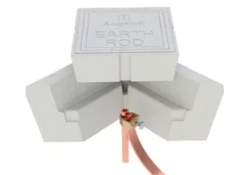
Additionally, should your design require the inspection pit to be installed in a basement, then, you will need to determine whether or not you will require an earth seal to prevent water flooding. (discussed below).
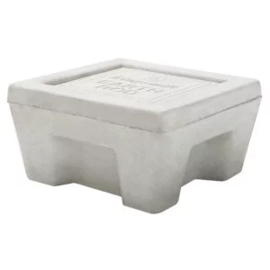
Finally, it is important to make sure that your pits are tested to BS EN 62561-5 for their withstand capacity, This, is to avoid fracture when installed in areas with heavy traffic.
Purpose: Connecting Clamps serve to connect the earth conductor to the earth electrode.
What to keep in Mind: Different types of connections exist depending on the combination of the conductor and electrode that you are using.
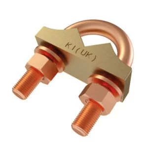
Since the clamp serves as the bridge between the conductor and electrode, it is critical that the clamp is also conductive and made to last over time. For that reason, the standard prescribes specific materials to be used for clamps including the metal alloys. The standard requires that the alloy used in the casting consist of at least 75% copper. Additionally, any U-Bolts used in these clamps should be made of 99% HD copper.
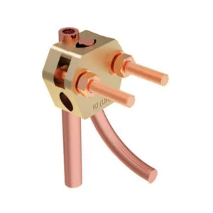
Many products in the market fail to meet these standards since this is one of the easier areas for manufacturers to cut costs and increase their margins. Be sure to inquire about the copper composition of the alloys used in the connecting clamp. Additionally, make sure to inspect your U-Bolts to ensure they’re not an inferior metal coated in copper as this copper coating will scratch away leaving the less-conductive metal surface exposed below.
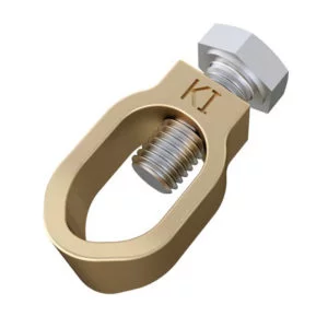
Use of 60/40 brass should be avoided, due to its poor corrosion resistance and tendency to develop stress fractures long after installation. As mentioned earlier, your system is only as strong as your weakest link.
Purpose: Exothermic Welding is another way of connecting copper to copper and copper to steel through a self-contained welding process. Unlike bolted and compression connections (which can loosen and corrode over time), this is a permanent connection and is used typically in substation gridwork construction and for making equipotential bonding connections in structures.
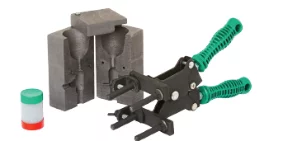
The key advantage of exothermically welded joints is that they take 100% of the rated fault current of the conductors being joined. They are permanent, mechanically strong and being of 97% copper, they are extremely resistant to corrosion. Such joints are the premier connection method for any earthing system.
It’s important here to make sure that you have good quality weld metal.
Otherwise, you’ll end up with joints that not only look tarnished, but are also inherently weak.
For more information on the types of connections available, please visit our website at
https://www.kingsmillindustries.com/products/exothermic-welding/mould-types/.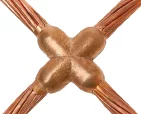
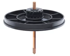
Purpose: Earth rod seals are not always required, but are designed to create a watertight seal between the earth rod, earth electrode, and the waterproof membrane in order to prevent ground water seepage. Earth rod seals are used where the design prescribes that the earthing point or inspection pit be located within the structure itself. This implies that the earth electrodes will have to pass through the structures floor slabs and will pierce the waterproof membrane.
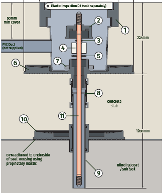
What to keep in Mind: The British standard prescribes that earth seals should be tested to withstand 5 bars of pressure for at least 24 hours. While this is the minimum requirement, additional length testing can be done to further confirm product capability.
Additionally, if your site requires a waterproof seal, we recommend a plastic pit to be installed in conjunction, as a concrete pit will not work. Give us a call to ensure your earth pit selection is compatible with your requirements.

Final Words
In general terms, we have now covered the various categories of earthing materials available. As the selection may appear overwhelming, the team at Kingsmill Industries is always ready to help you navigate through your selections and questions. Browse our website, call us, or send us an email for any additional information you might need to help you with your earthing or lightning protection systems.
For any further questions, please don’t hesitate to reach out to us at [email protected]. Or contact us through our website to submit a query.


