It is well-known that numerous sorts of faults and hazards can occur in electrical substations during their lifetimes. Among many other threats, substations are affected by:
- lightning strikes,
- fog, rain and snow,
- solar overheating,
- windborne materials
- and other atmospheric conditions
A basic safety measure consists of installing fences along the perimeter of the substation in order to prevent incidents of trespassing, stray animals foraying into the substation, and more importantly, unqualified individuals gaining entry into the area.
In fact, the role of any protection system is not to prevent a fault from occurring but to effectively deal with it if one happens. A complete protection system is always recommended for the safety of the personnel and to help protect the power network and associated equipment. Different systems of protection work collectively within electrical substations.
Protection should be able to detect the faults as quickly as possible and isolate the faulty part or equipment. Thus, minimising:
- risk of disturbance and instability in the whole system
- risk of possible damage to nearby healthy equipment
- damage to the faulty items
It is worth noting that electric shock hazards for anyone entering the perimeter of the substation is the highest risk, because it can occur with or without physical contact with equipment. In the same context, other elements put individuals in danger if they are inside a substation. Even if the substation is out of service, such as:
- Electrical conductors
- High-voltage lines entering the substation
- High-voltage busbar
- Capacitor banks,
- Battery rooms,
- Circuit breakers
- Metal component inside the substation
Most energy companies are actively monitoring how the networks are working and they monitor the state of each component within the power system.
Such companies are well placed to evaluate the weakness of the networks with regard to weather impacts. For instance, systems have been developed to provide a way to monitor harmful lightning activity.
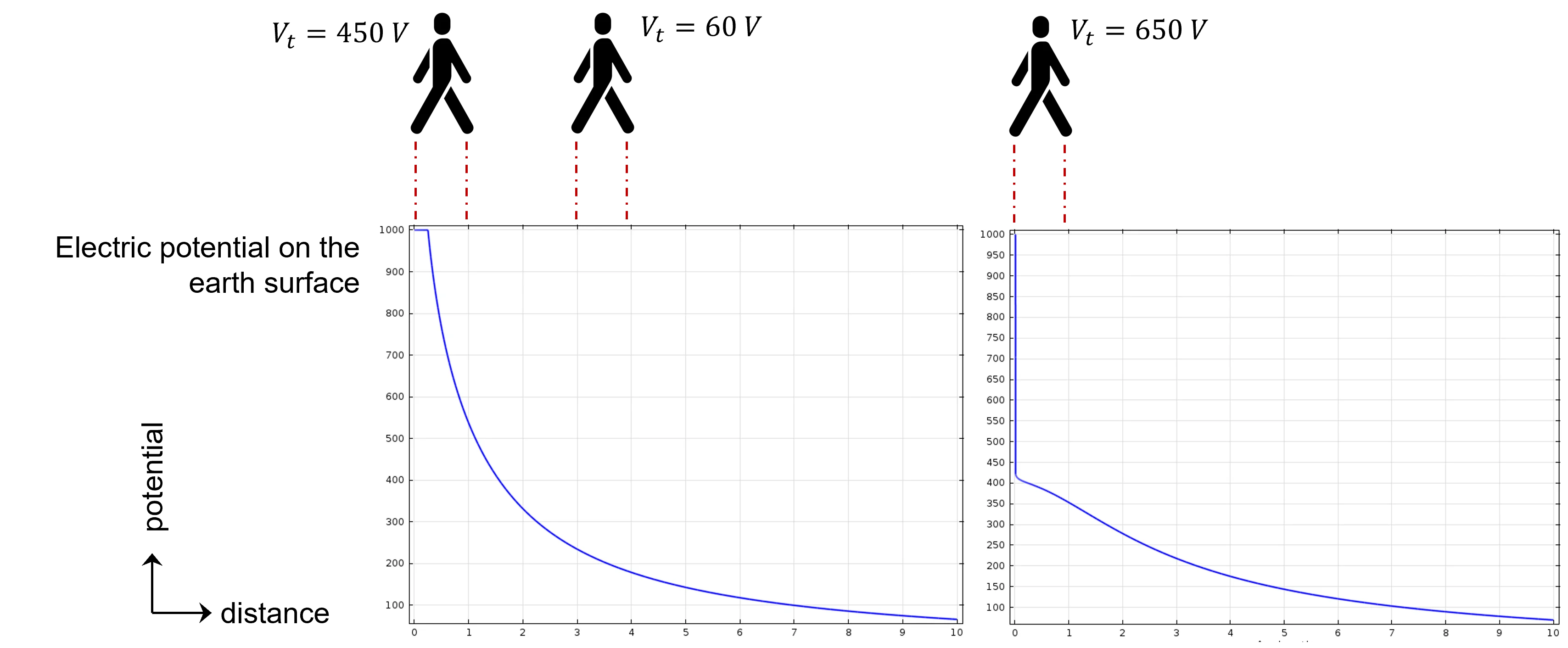
Under fault events, current flows through the earthing system causing an earth potential rise (EPR), also known as ground potential rise (GPR), and results in a non-uniform distribution of the potential on the earth surface.
As defined in IEEE Std 80, the GPR is “The maximum electrical potential that a ground electrode may attain relative to a distant grounding point assumed to be at the potential of remote earth. This voltage, GPR, is equal to the maximum grid current multiplied by the grid resistance”. Figure 2 gives an example of the electric potential distribution on the earth surface accompanied by the equipotential lines in the ground.
As can be seen in this figure, the potential distribution on the earth surface is not uniform – increasing as getting closer to the injection point.
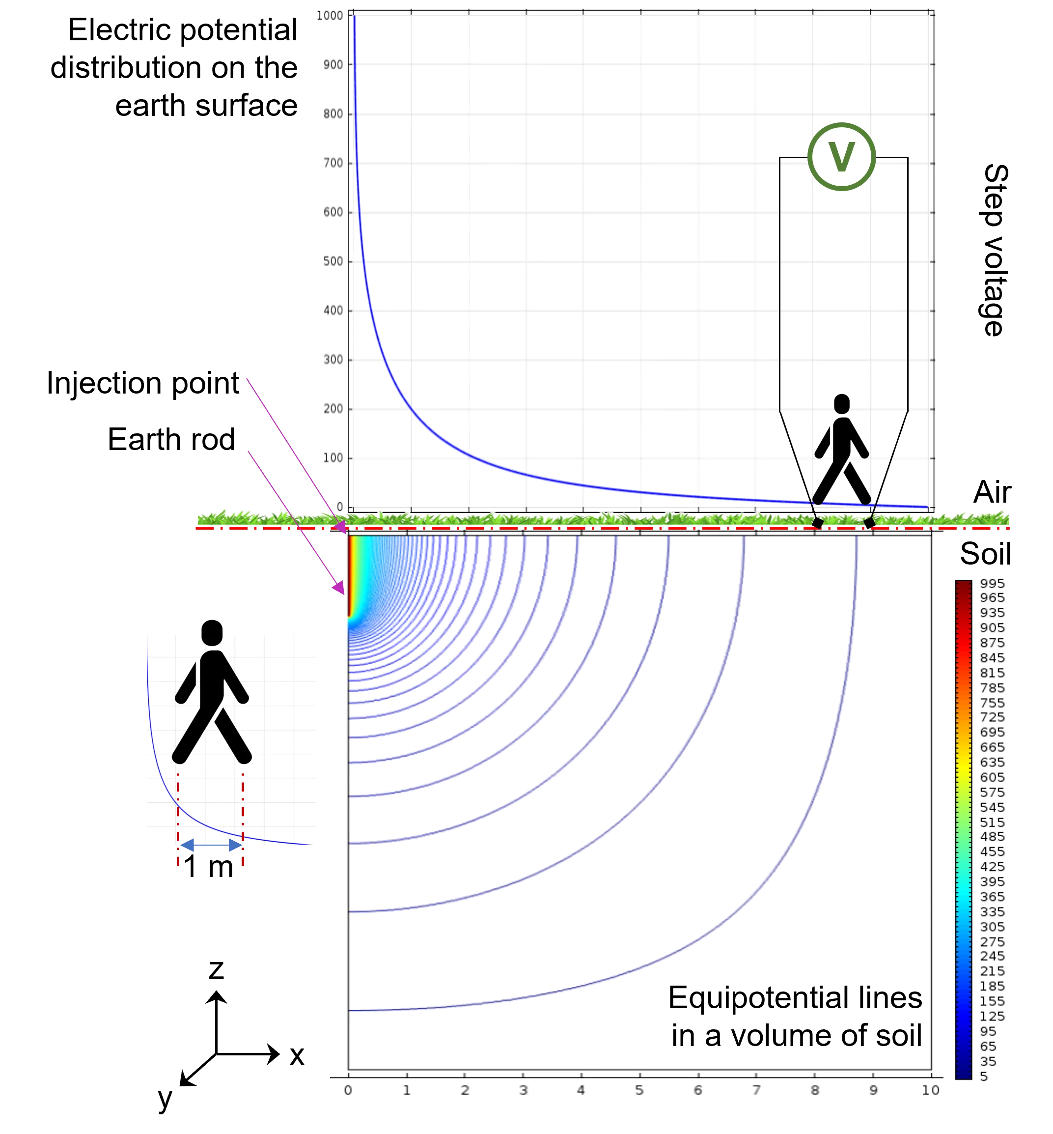
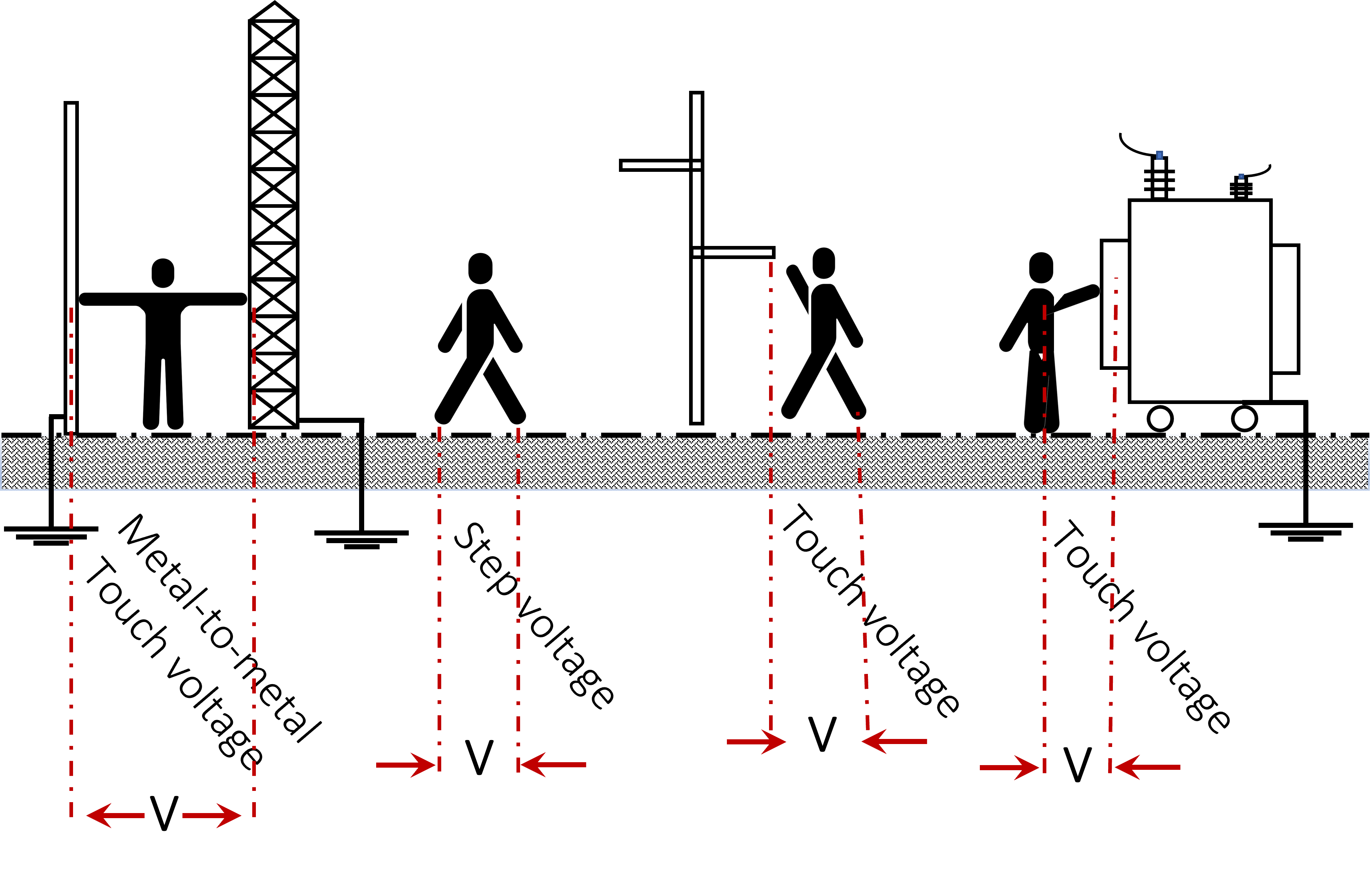
This distribution, called a potential profile, might result in a potential difference (i.e., step voltage) between the feet of any person walking in the surrounding environment – the potential difference that is experienced by an operator bridging a 1 m distance. Indeed, step voltage depends on multiple factors such as the weight, state and position of the person, the fault current, the soil resistivity, and so on. Figure 3 illustrates some examples of step voltages computed from two different earthing systems of simple configurations.
Anyone standing near the fault location can receive a life threatening s electrical shock from either the presence of a dangerous potential difference between the earth and a metallic object that a person is touching or resulting from the potential gradient on the earth surface.
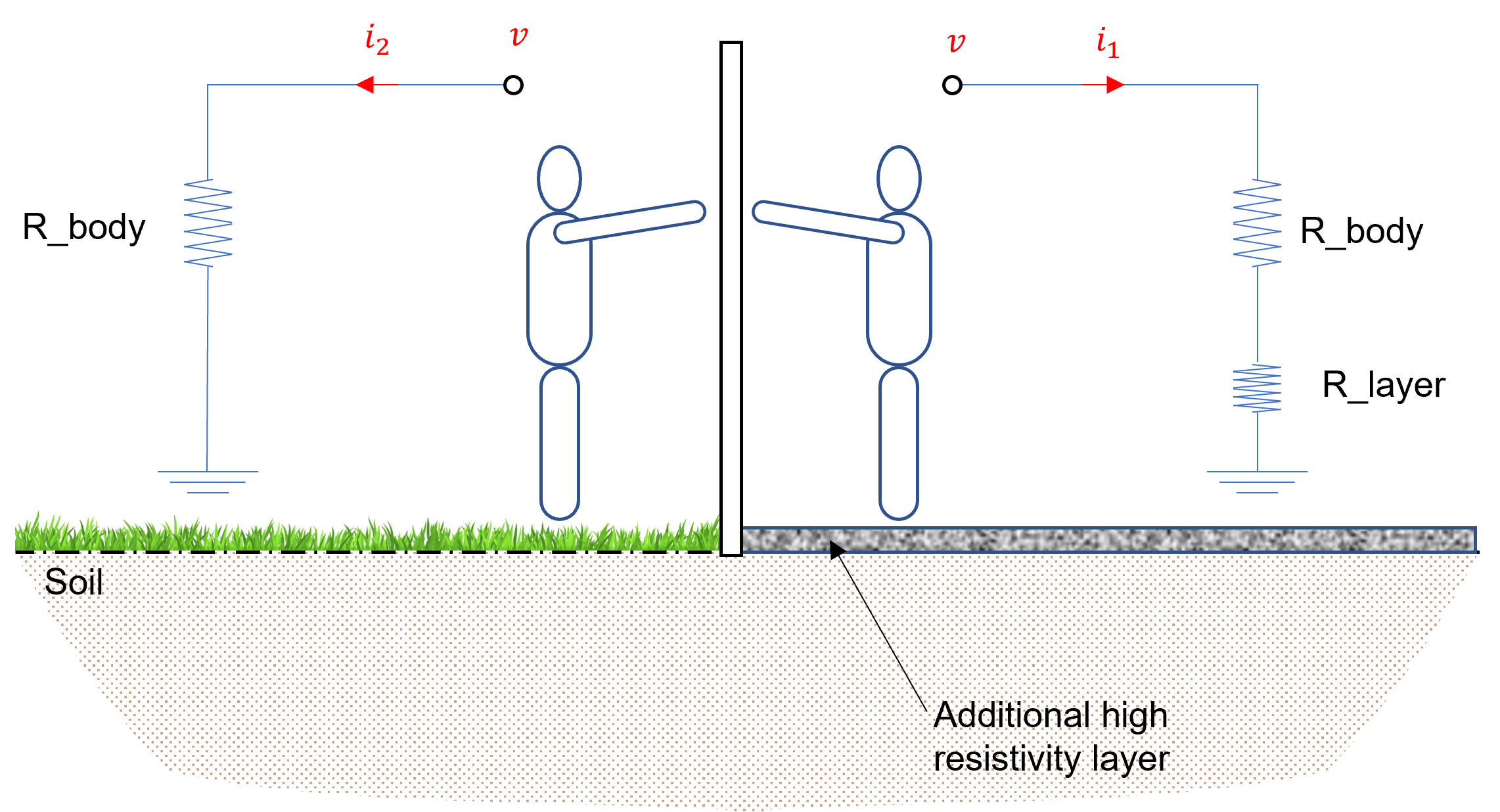
By definition (IEEE Std 81), the touch voltage represents “the potential difference between the earth potential rise and the surface potential where a person could be standing while at the same time having a hand in contact with a grounded structure or object”. Figure 3 illustrates a graphical representation to show the step and touch voltages within the electrical substations.
It should be noted that the metal-to-metal touch voltage usually occurs when metallic objects or structures within the substation site are not bonded to the earthing system.
In addition, touch voltage measurements can be with or without the equivalent body resistance included in the measurement circuit.
For safety and protection reasons, the design of an effective protective earthing system is mandatory in most electrical installations. In principle, an earthing system should safely carry electrical currents into the soil under both normal and fault conditions via its low resistive path to the ground. It should also work in conjunction with the protective systems in order to minimise any possible risk for a person whilst in the vicinity of the system.
In the case of electrical substations, an earthing grid is recommended to improve the distribution of the electric potential profile as well as reduce the resistance of the entire earthing system. Figure 4 illustrates three examples of typical square earthing grids without rods.
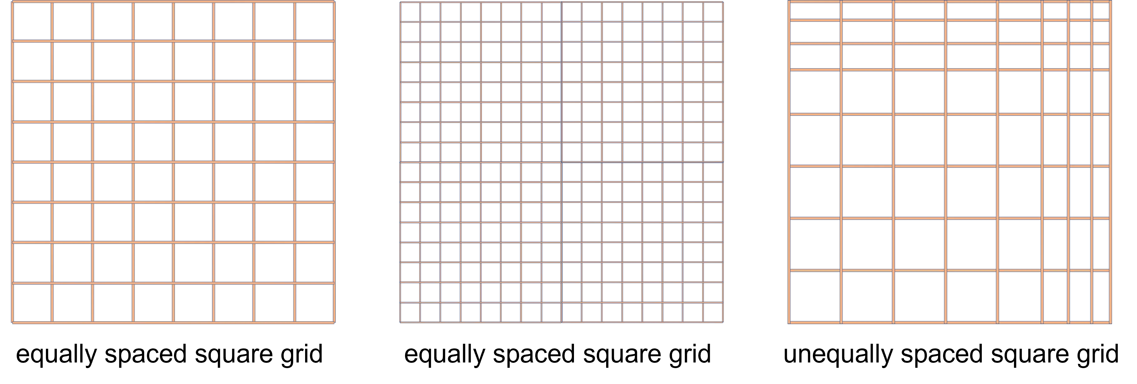
Another significant issue that should be considered during the design phase is the mutual coupling effect between earthing conductors. Therefore, an earthing system should be designed by specialised parties and in compliance with the safety regulations.
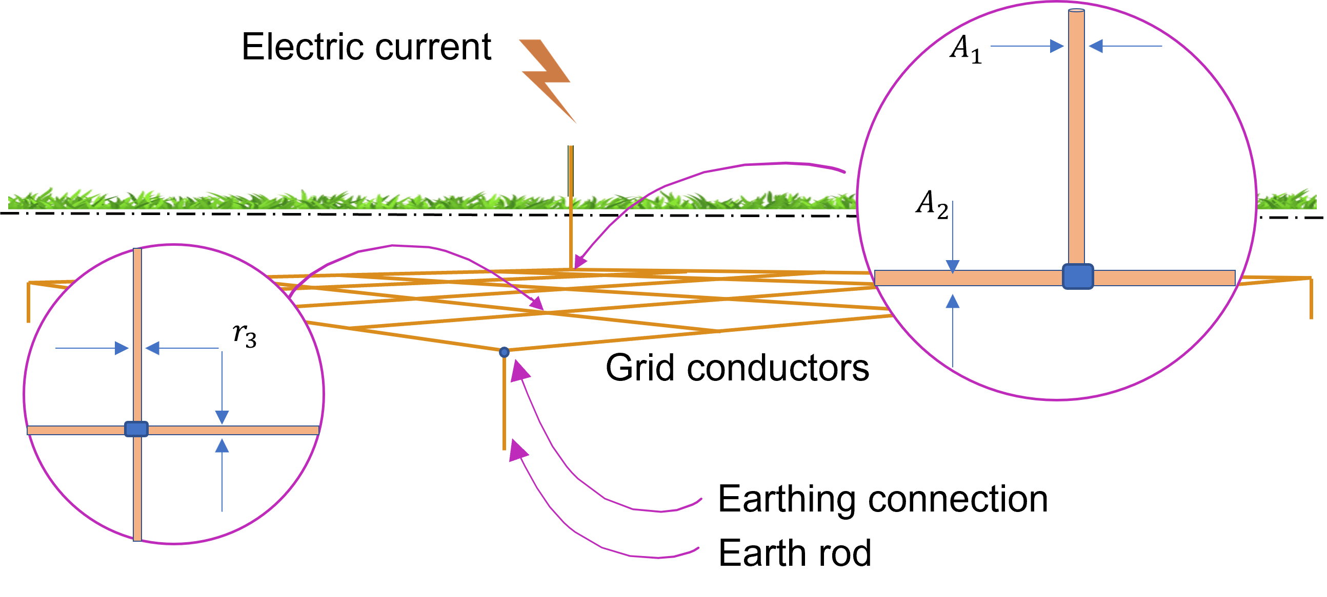
In general, the earthing grid will cover a large area and may have equally or unequally spaced conductors either in square or rectangular shape. Figure 5 shows a representation of a large-scale earthing system.
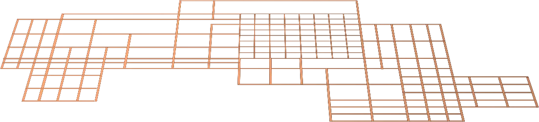
Each configuration is characterised by its own potential profile and expected GPR. In fact, these parameters, along with the earthing resistance, are affected by some factors such as soil resistivity and fault currents. The composition of the surrounding soil helps selection of the appropriate material that can be used in the earthing system – resistance against corrosion.
Sufficient data must be gathered for a substation, carrying out a couple of horizontal and vertical soil resistivity surveys. An effective modelling of the soil resistivity profile is also required to complete the design of the earthing system.
[1] IEEE Std 367:2012, IEEE Recommended Practice for Determining the Electric Power Station Ground Potential Rise and Induced Voltage from a Power Fault.
[2] IEEE Std 80:2013, IEEE Guide for Safety in AC Substation Grounding.
[3] IEEE Std 81:2012, IEEE Guide for measuring earth resistivity, ground impedance, and earth surface potentials of a ground system.