Energy consumption needs are expanding rapidly around the globe in the recent decades. Indeed, there are many reasons behind this enthusiasm such as the increase in population as well as the rise in commercial and industrial activities. To meet these needs and satisfy the clients at different levels, recourse to new energy sources, along with the construction of new infrastructure for the transmission, is therefore essential. This point encouraged the exploration of new lines of research in the field of transport, protective systems and production of electrical energy. Regarding the latter, new long-term ecological strategies have been adopted in the UK and around the world. It consists of a gradual integration of clean energy sources into electricity networks. Energy is a complex process as it is possible to convert it into different forms, transport it, store it in some forms and use it in various end use modes in innumerable kinds of places.
Appropriate transport and distribution systems are needed either for direct use or for further conversion into other useful forms to supply various places of consumption. It is well known that the electrical energy is produced, transported and distributed in high voltage transmission networks. Transmission is mostly conducted in alternating current – HVAC. In fact, this type of transport is not always the best practical way when it comes to interconnecting renewable energy sources with grids. The resources of these energies are often located in remote regions such as at sea, in uninhabited areas or even in desert regions. For this purpose, transmission in direct current (i.e., HVDC) is recommended under such circumstances.
In general, electricity from centralised power generation is more appropriately transmitted over distances with different lengths by transmission and distribution networks. In order to fulfil the safety limits and requirements, every element within the electricity system such as pylons, overhead lines, substations etc – should be designed in accordance with the relevant national and international standards. The electrical energy, from generation to consumption, passes by multiple adaptions where different levels of voltages may be required. Step up and down of the voltage level is set up through the electrical substations.
Voltage level from high to low, or the reverse, is basically carried out within the electrical substations so it is suitably delivered to customers. These substations can also perform any of several other important functions such as measuring electric power qualities and connecting communication signals. In this light, various types of substations are developed to meet the requirements of the customers. These types usually depend on the voltage level, which depends on additional factors like the number of the customers supplied. Indeed, other parameters will be affected by the selection of the voltage level, including the size of the substation and the protective systems. Table I gives typical parameters associated with the electrical substations in the UK.
Substation type | Distribution | Primary | Electric Grid | |
Bulk Supply Point | Grid Supply Point | |||
Voltage level | Below 11kV | 33kV to 11kV | 132kV to 33kV | 400kV to 132kV |
Average size | About 20 m^2 | 25×25 m^2 | 75×75 m^2 | 250×250 m^2 |
Customers supplied | Up to 500 | Up to 30,000 | Around 100,000 | More than 200,000 |
Table 1. Typical parameters associated to the electrical substations in the UK
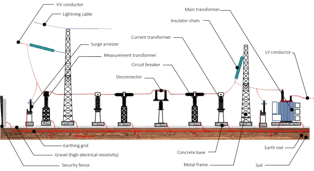
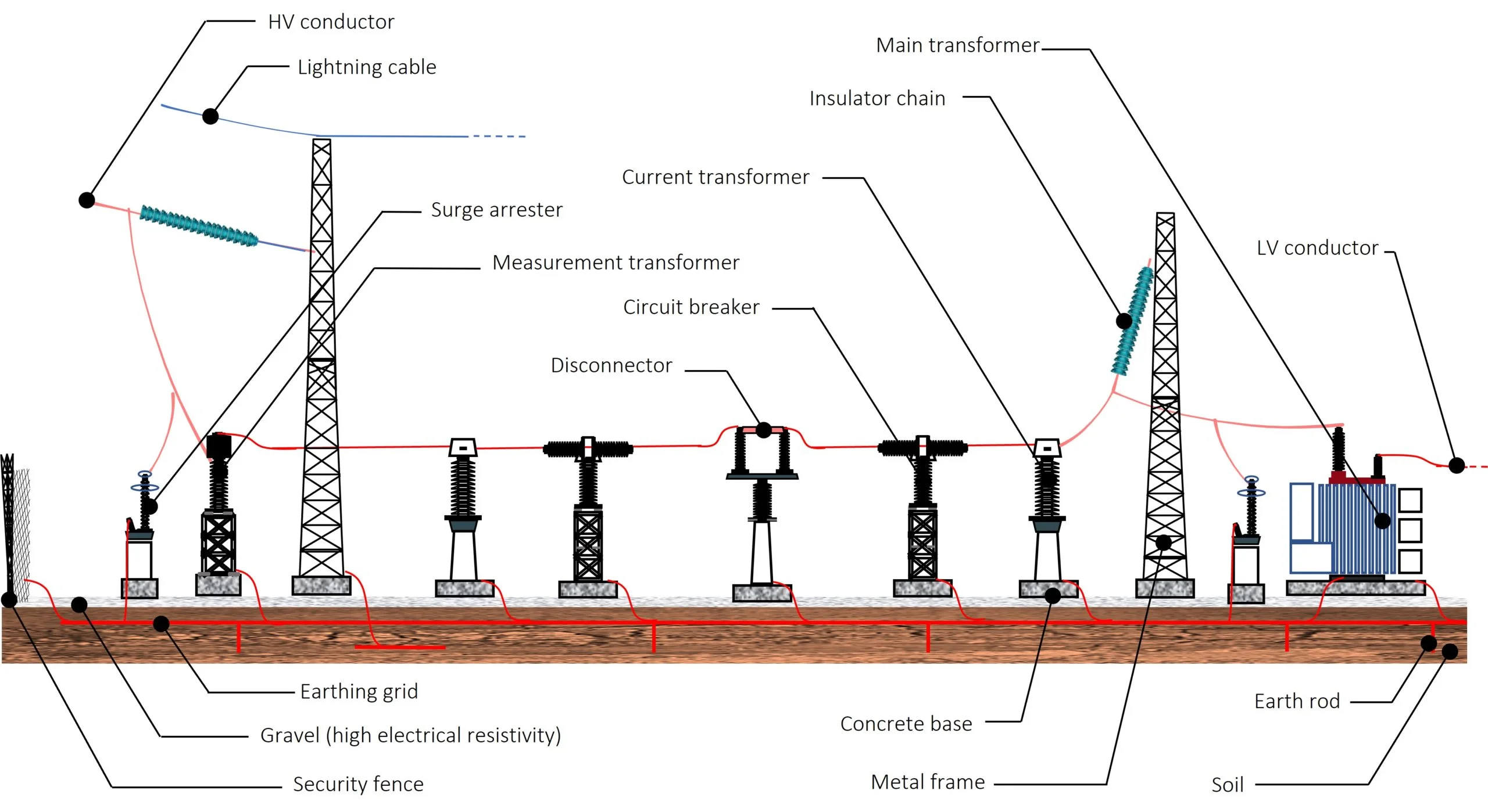
A route length of more than 7,000 km of overhead lines represent a part of the UK Electricity Transmission system, including about 700 km of underground cable and more than 300 substations. Basically, a substation includes different components where the main one is the transformer/s, used to adjust the voltage levels. This can be achieved by changing the voltage levels between high transmission voltages and lower distribution voltages, or at the interconnection of two different transmission voltages. Substations generally have switching, protection and control equipment, including measurement and monitoring equipment. Circuit breakers are usually used in large substations to interrupt any short-circuits or overload currents that may occur on the network. Additional protection measures should also be considered such as surge arrester and fuses for protection of distribution circuits. Figure 1 shows a simplified representation of an electrical substation.
As can be seen in this figure, different protection measures should be considered in this system to protect both individuals and equipment. In general, high voltage installations require an effective earth-termination system in order to protect people against excessive step and touch voltages. As shown in Figure 1, all metallic parts are earthed to prevent accidental contacts by workers with energised elements. In addition, a layer of surface material (e.g., gravel in Fig. 1) of high electrical resistivity is usually used in substations. This layer can help in limiting the body current by adding resistance to the equivalent body resistance.
During the lifetime of substations, there are many different sorts of faults and hazards that can occur. In most cases, the causes of these malfunctions are related to weather conditions such as:
- Lightning strikes,
- Fog, rain and snow,
- Solar heat,
- Windborne materials
Pollution within the substations should be considered since it can engender a flashover on the high voltage insulators (pollution of the insulating surface). Indeed, It is obvious that the common cause of damage consists in the ageing of the equipment and/or the degradation of the insulation material. These causes can result in several significant issues. The electrocution for anyone entering the perimeter of the substation is the one with the high risk because it can occur with or without physical contact with equipment. In the same context, different elements put individuals in danger if they are inside the substations such as:
- Electrical conductors
- High-voltage lines entering the substation
- High-voltage busbar
- Capacitor banks,
- Battery rooms,
- Circuit breakers
- Metal component inside the substation
Most of the energy companies are actively monitoring how the networks are working. They are well placed to evaluate the vulnerability of the networks to weather impacts. Different monitoring systems have been developed to provide a way to monitor lightning activity that can be harmful. For instance, Jupiter OLS is a site-specific, high-speed video based lightning location system that detects 100% of lightning return strokes and pinpoints the location of lightning strikes with unprecedented accuracy. This active monitoring system and many others should be designed to help plan and prioritise the work to enhance the resilience of the sector to current weather events. Furthermore, oil-filled switchgear and transformers as well as any other regulators and capacitors need to be fully isolated and grounded.
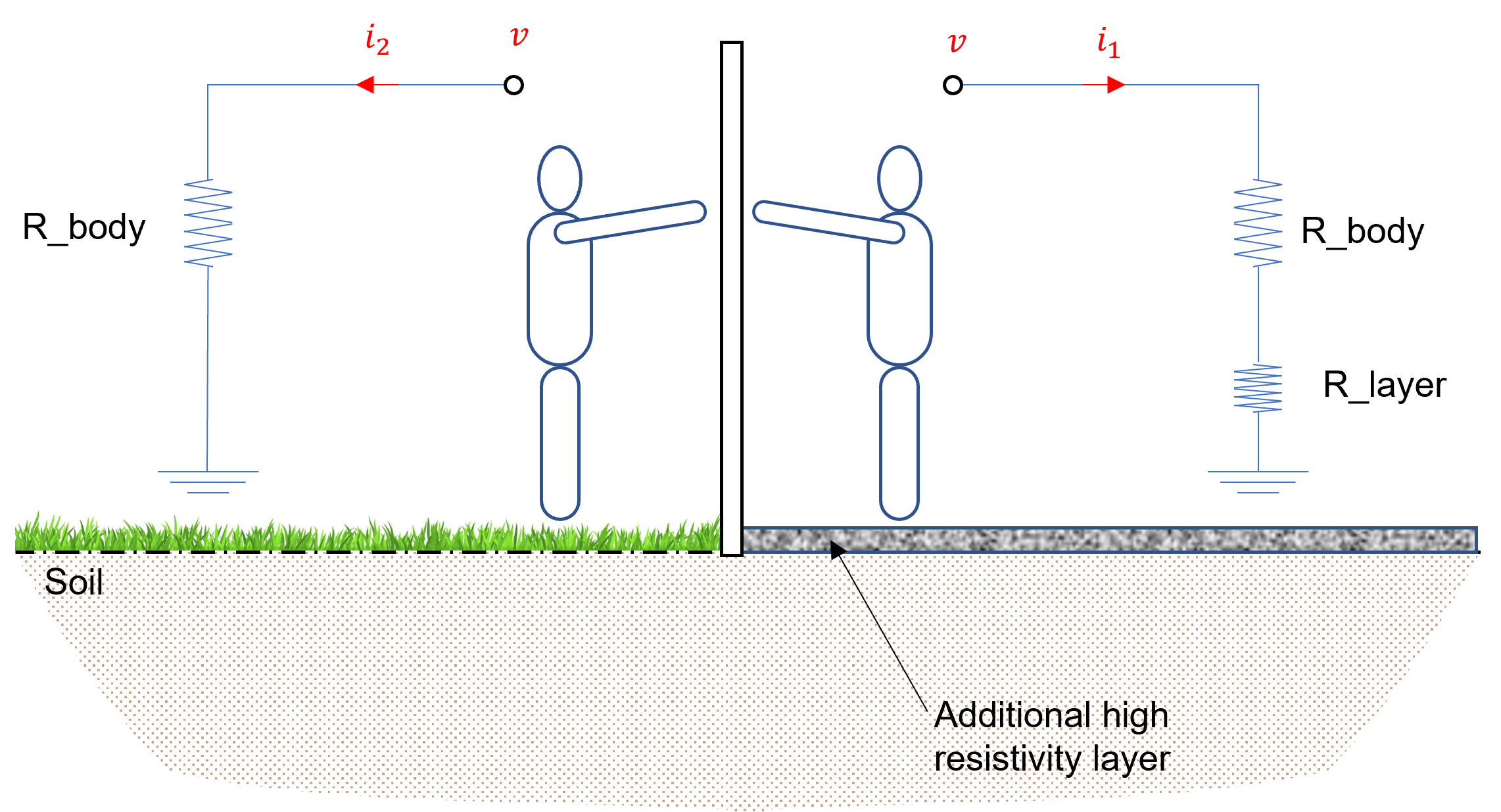
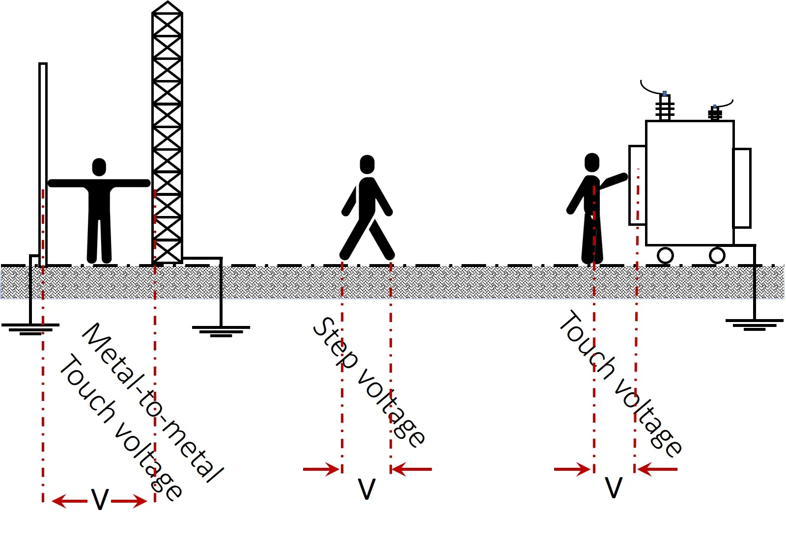
Anyone standing near the fault location can receive a dangerous electrical shock owing either to the presence of a dangerous potential difference between the earth and a metallic object that a person is touching or resulting from the potential gradient on the earth surface. Figure 2 illustrates a graphical representation to show the step and touch voltages.
It should be noted that the step voltage is the potential difference, on the earth surface, that is experienced by an operator bridging a 1 m distance without contacting any earthed structure. By analogy, the touch voltage is the potential difference computed with respect to the surface potential where a person could be standing while at the same time having a hand in contact with (an) earthed structure(s). Metal-to-metal touch voltage usually occurs when metallic objects or structures within the substation site are not bonded to the earthing system.
For safety and protection intentions, designing a safe protective earthing system is mandatory to provide the shortest path to the effective flow of fault currents without exceeding the operation and equipment limits. In this light, a couple of national and international standards as well as regulations and rules have been published to identify the requirements of the earthing design and to define relevant parameters for structures, electrical equipment and systems. Among others, Table 2 gives example of standards proposed for the said matter.
| Standard | Title |
| IEEE Std 80 | Guide for Safety in AC Substation Grounding |
| BS EN 50522 | Earthing of power installations exceeding 1 kV a.c. |
| ENA TS 41-24 | Guidelines for the design, installation, testing and maintenance of main earthing systems in substations |
Table 2. List of Some Standards Used for Design Earthing Systems in Substations
These standards offer the necessary guidance and recommendations for the design, specification, inspection and periodic testing of earthing systems. It is worth noting that some standards and documents are indispensable for the application of the said standards. Engineers and designers should also take into account these guidance references such as:
- BS 7430: Code of practice for protective earthing of electrical installations,
- BS 7354: Code of practice for design of high voltage open terminal stations,
- IEEE Std 81: IEEE Guide for measuring earth resistivity, ground impedance, and earth surface potentials of a ground system.
- BS EN IEC 61936-1: Power installations exceeding 1 kV AC and 1.5 kV DC.
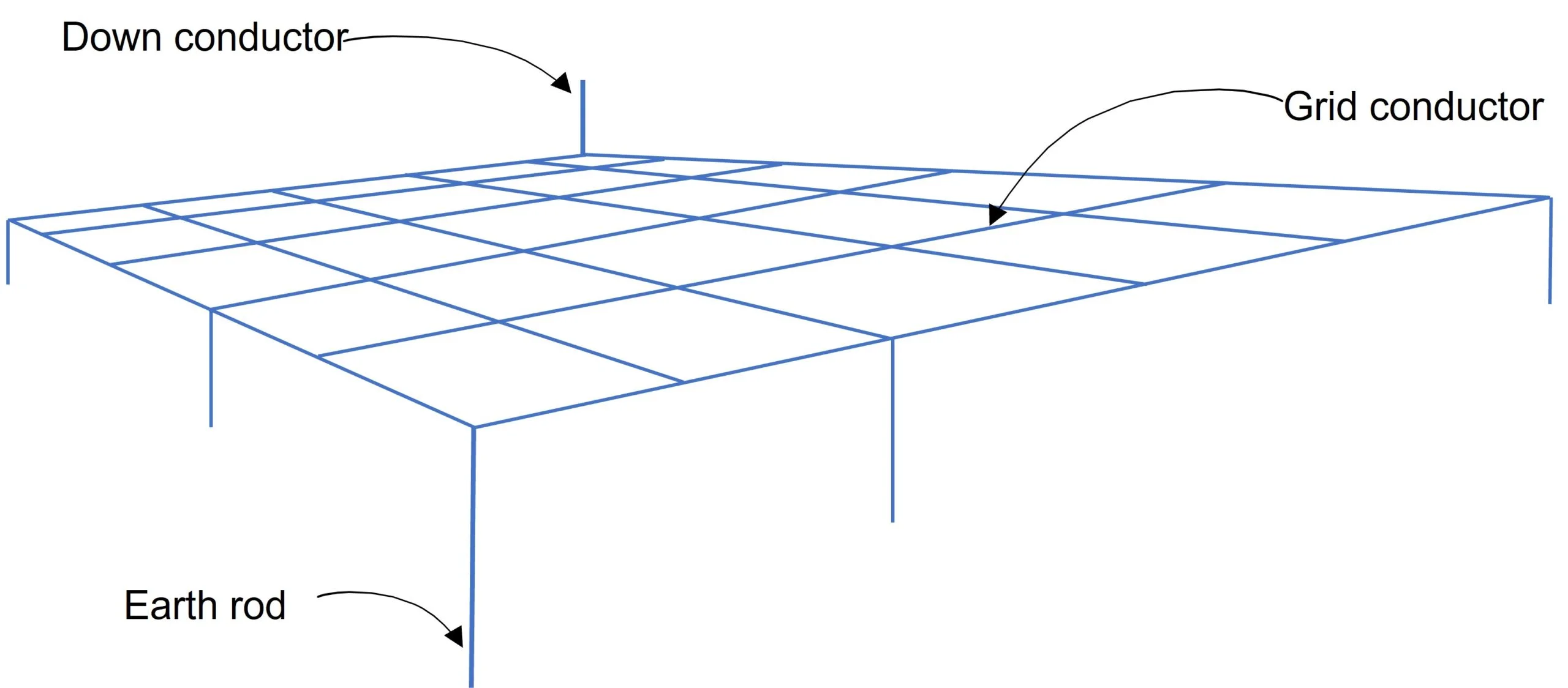
Under fault events, current flows through the earthing system cause an earth potential rise (also called, ground potential rise) at the injection points, and results in a non-uniform distribution of the potential on the earth surface. Both consequences can affect the safety of persons due to touch and step voltages. Therefore, the design of an appropriate earthing system is one of the most decisive parameters to ensure the safety of people, devices and equipment, and to improve the quality of electrical service. An earthing grid is recommended to improve the distribution of the electric potential and reduce the resistance of the entire earthing system. Figure 3 illustrates an example of a typical equally spaced square earthing grid with rods.
In practical situations, the earthing grid will cover a large area and may have equally or unequally spaced conductors either in square or rectangular shape. The length, number and position of the earthing grid can be different from one substation to another. It should be noted that the cross section of the conductors are designed to support fault or lightning currents.
Indeed, the grid resistance and the voltage gradients within a substation are directly dependent on the soil resistivity. The composition of the latter can help selecting the appropriate material for the earthing system – resistance against corrosion. For these reasons, sufficient data must be gathered for a substation, carrying out a couple of horizontal and vertical soil resistivity surveys. An effective modelling of the soil resistivity profile is also required to complete the design of the earthing system.
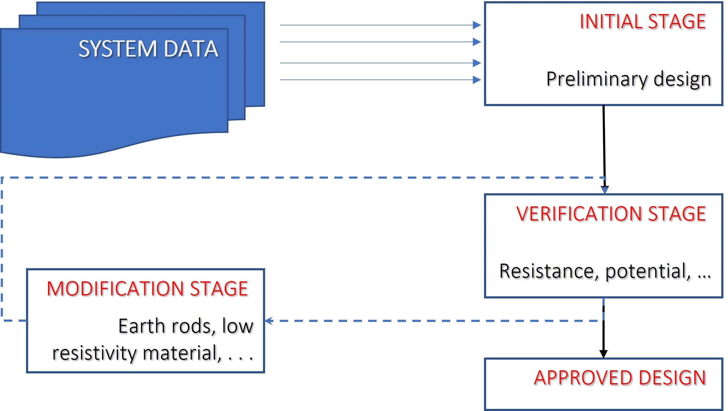
It is clear that any process is complicated if we look at it from the very low level with all details included at once. For this purpose, the design procedure of substation earthing is simplified so that designers can follow it according to the requirement of the IEEE Std 80. Let’s begin with the high level chart shown in Figure 4. This chart groups the design procedure into four main stages.
In this figure, one can see that the shortest pathway contains three stages; initial, verification and approval stages. In a realistic situation, a couple of modifications are usually done to serve the requirements of safety given by the standard regulations. In fact, each stage contains several steps and instructions. It should be noted that engineers and designers should obtain accurate field data (e.g., soil resistivity) and define acceptable ranges for design variables for the considered earthing system.
Kingsmill industries are familiar with such projects, especially in the field of earthing system and soil resistivity measurements. Likewise, we aim to satisfy the customers demand for reduced construction costs by using optimisation methods to design reliable, efficient and economical earthing systems, which comply with the national and international regulation of safety and protection.
[1] IEEE Std 80:2013, IEEE Guide for Safety in AC Substation Grounding.
[2] BS EN 50522, Earthing of power installations exceeding 1 kV a.c.
[3] ENA TS 41-24, Guidelines for the design, installation, testing and maintenance of main earthing systems in substations
[4] IEEE Std 81:2012, IEEE Guide for measuring earth resistivity, ground impedance, and earth surface potentials of a ground system.
[5] BS EN IEC 61936-1: Power installations exceeding 1 kV AC and 1.5 kV DC.
[6] BS 7430: Code of practice for protective earthing of electrical installations.
[7] BS 7354: Code of practice for design of high voltage open terminal stations.
[8] Adaptation to climate change report, 2011