Human-beings, animals and structures are potentially exposed to several types of electric threat of different characteristics. The main are direct lightning strikes and the consequences resulting from the discharges. Risks associated with a lightning strike are of two types: those linked to a direct lightning strike, and those which are consequences of the discharge of the lightning. Figure 1 illustrates examples of both direct and indirect lightning discharges and their effects on human-beings, buildings, structures and the surrounding environments.
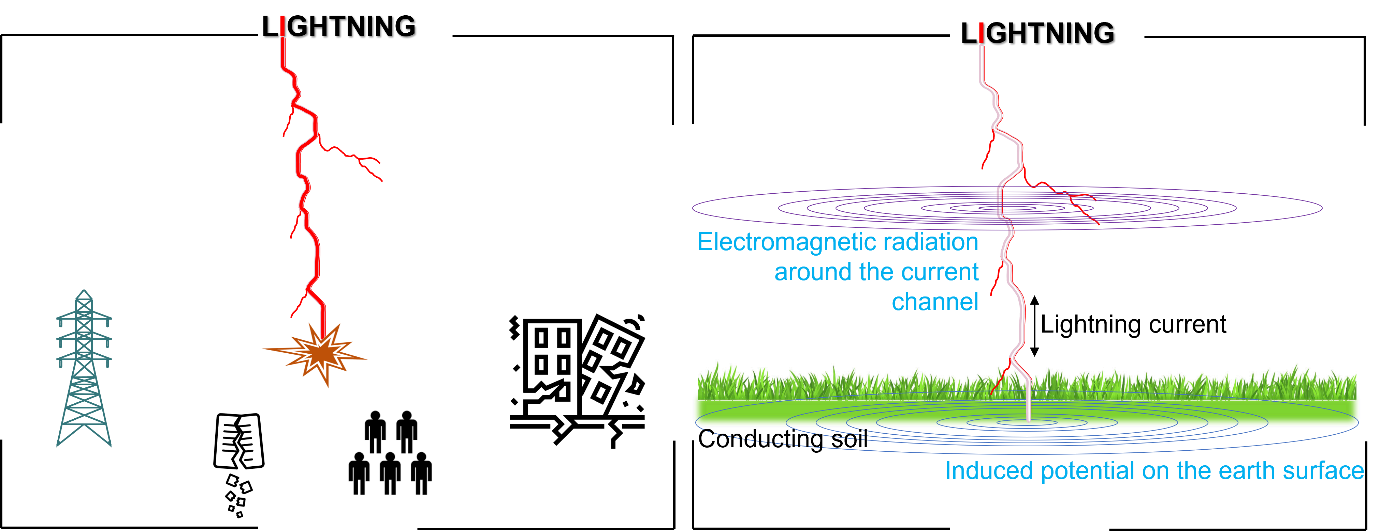
Overvoltage effects can be grouped into two classes as follows:
- those which are of a direct consequence from lightning strike. For example: thermal, electrical, auditory and ocular effects
- those resulting from indirect effects of a lightning strike. For instance, burns related to a fire, falling objects, and so on.
Regarding the structures and industrial installations, a direct lightning discharge can generate several damages and losses. Examples include:
- fires,
- falling trees causing accidents,
- explosions of flammable liquids or gases,
- destruction of bell towers, television antennas, electrical and electronic equipment,
- damage to power lines or telephone networks,
Furthermore, lightning can cause damage to industrial (e.g., port facilities, airport ground installations, oil refineries, fuel tanks, . . . etc.) and agricultural sites (e.g., silos, farms, fish farms, . . . etc.). Overall, the previous consequences, damages and outages can have a considerable effects on the economy of a country, which is then affect in different ways the life of its people.
It should be noted that the psychosomatic consequences of lightning strikes or overvoltage should not be overlooked.
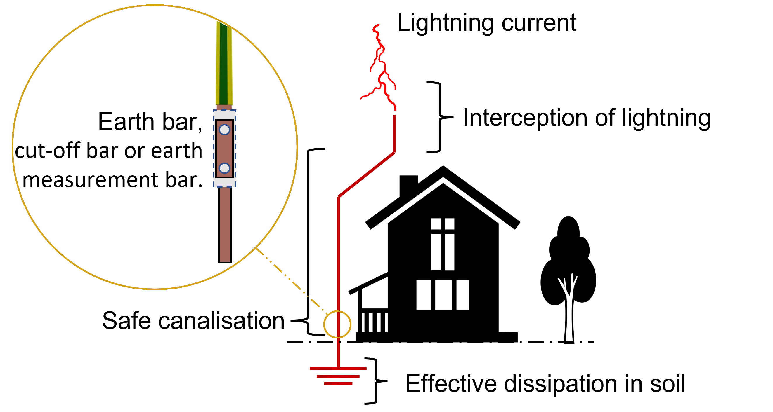
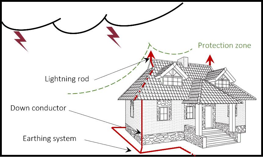
Lightning affects humans directly and/or indirectly [1–4]. It poses a major risk of property damage by causing fires and power system outages. It also causes surges that damage electronics. To protect humans as well as these structures and equipment from lightning, the installation of an adequate lightning protection system is highly required. The understanding of the functionality of these protective systems is described previously in Lightning Protection Systems piece. Briefly, lightning rods are designed to protect a building from direct lightning strikes by directing atmospheric discharges to the earth through earthing systems. This latter should be properly designed for an effective dissipation of lightning currents.
This type of protection is designed to prevent risks by warning when storms are current. Active protection allows for the complementation of special operating procedures and reinforced surveillance.
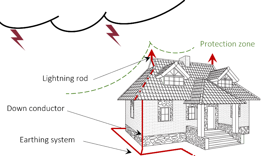
Intelligent assistance system allows measuring the health states of every single protective device via a cloud connection and provides additional digital services. Indeed, active protection also offers a simple and comprehensive analysis of the system. Possible disturbance variables can be detected before there is a failure in the system, which facilitates the service planning and maintenance operations.External lightning protection systems use lightning conductors, products and accessories that can control the connection of lightning on structures, and simultaneously disperse its energy to the earth as shown in Figure 2. In most cases, the passive protection may limit the electromagnetic disturbances of lightning by the implementation of a set of measures, which control of the earth potential rise and minimise the touch and step voltages. Mesh composed by bare copper conductor is also an effective technique to increase the protection zone.
It should be noted that all modes of transmission of electromagnetic disturbances caused by lightning should be considered. Therefore, all link and connection should be taken into account such as the electric energy lines, telephone lines, power cables, metal pipes, the soil and the air. Since the risks and costs involved increase, more expertise is required for the analysis and implementation of these protective systems. In addition, to be effective, these protection systems must be studied at an earlier stage with the initial design of structures and buildings. Maintenance and verification procedures must also be put in place.
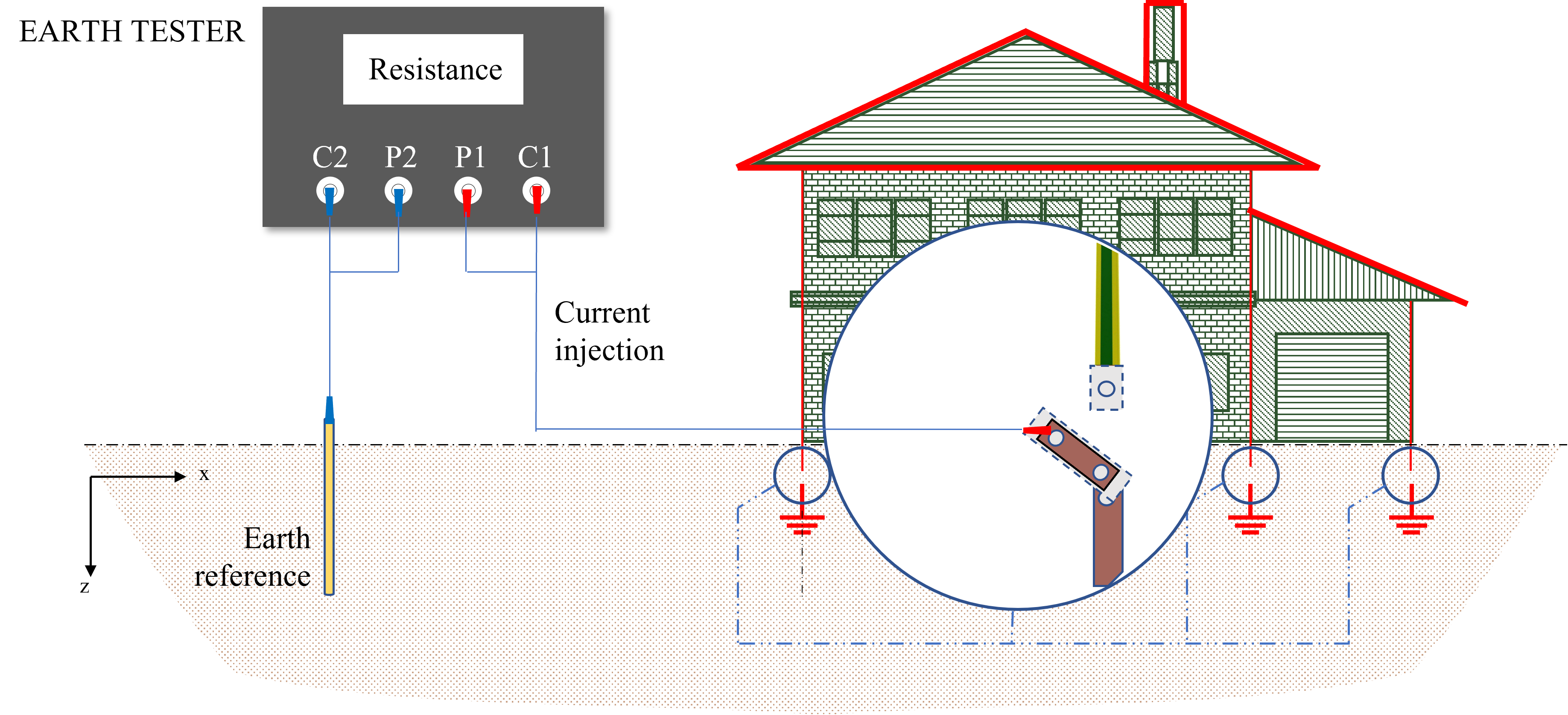
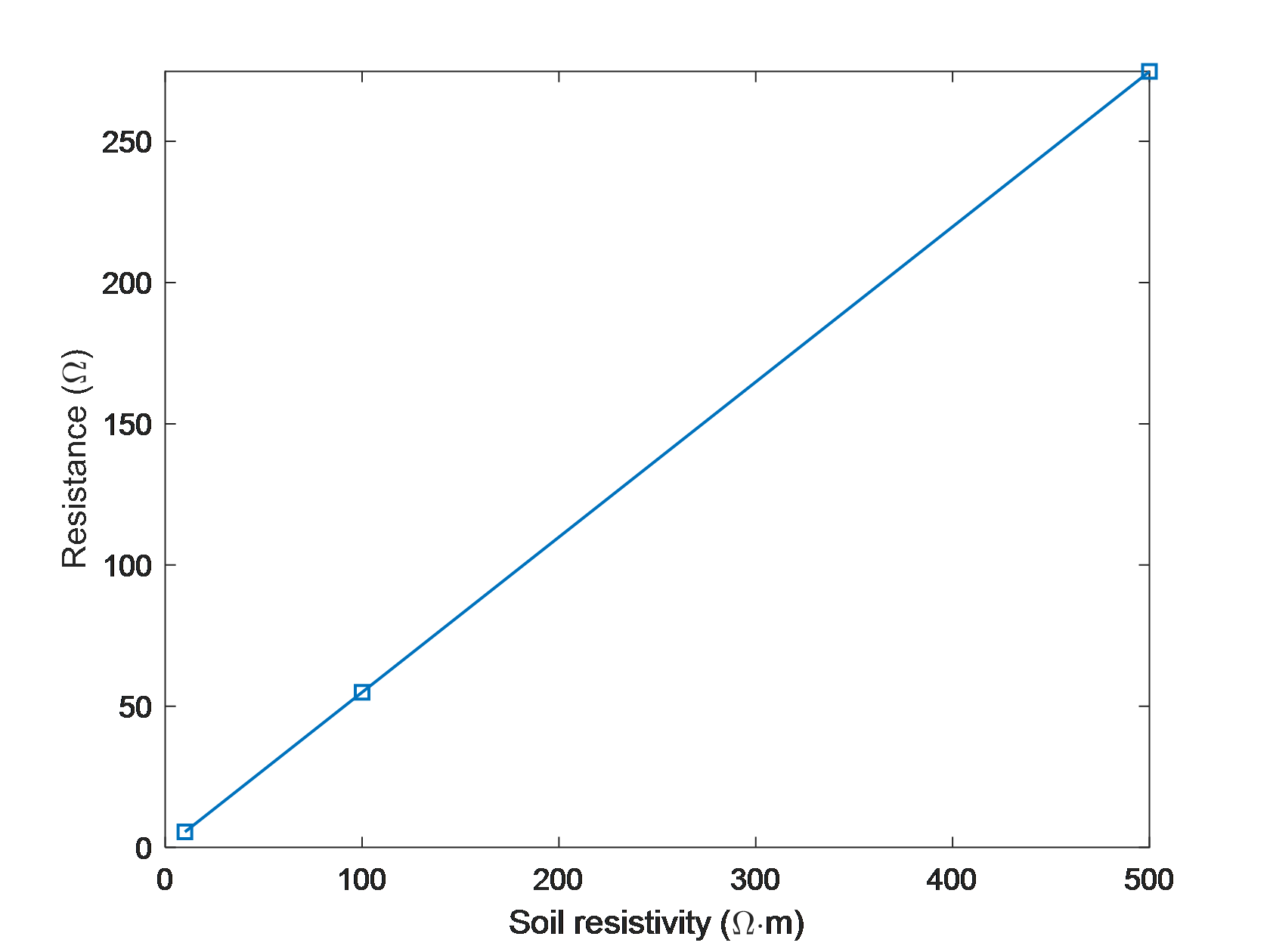
An earthing system represents an important component in any class of protection, helping dissipate the fault and lightning currents into the earth. In other application, the system can be used as a reference signal. In general, the effectiveness of any earthing system depends on obtaining a low resistance between the earthing systems and the earth mass. This resistance depends on several parameters and factors. Figures 3 and 4 show examples of the resistance of earth electrodes buried in soils with different resistivities, computed for different length and radius.
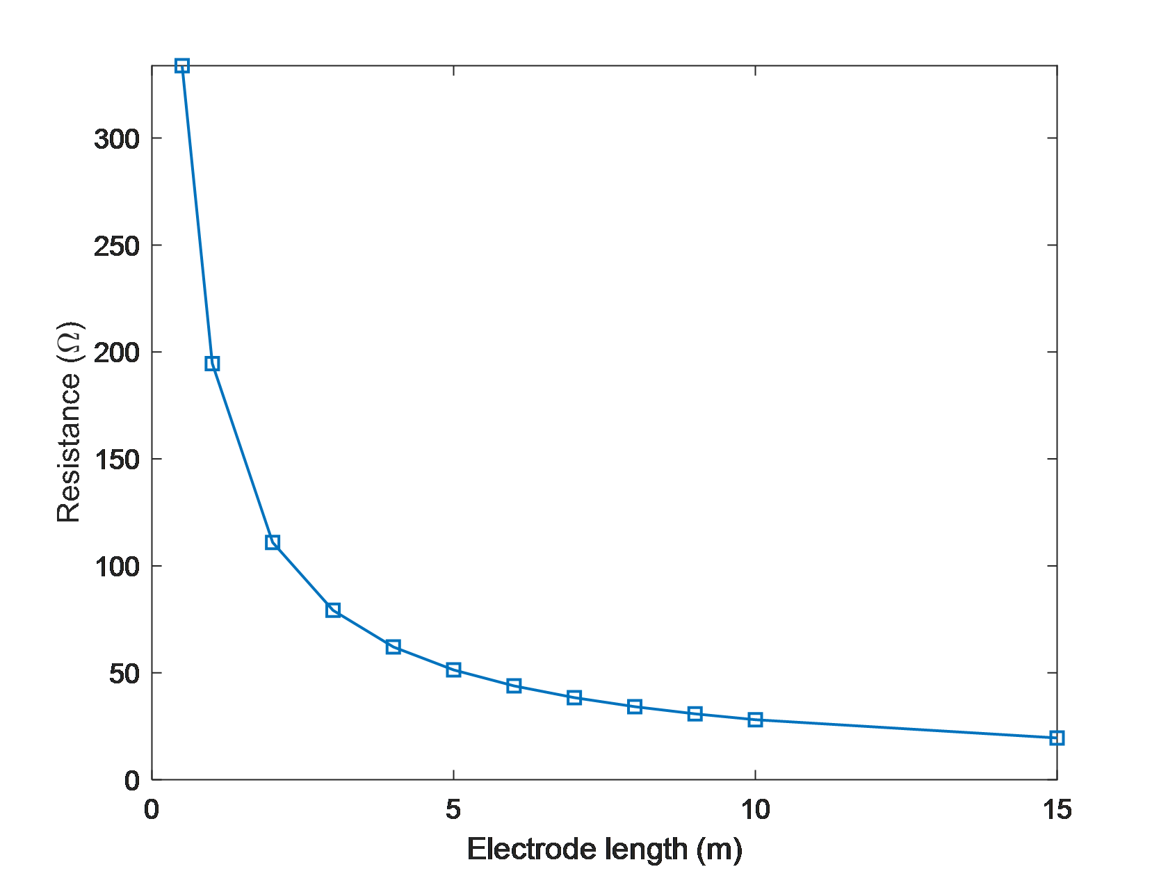
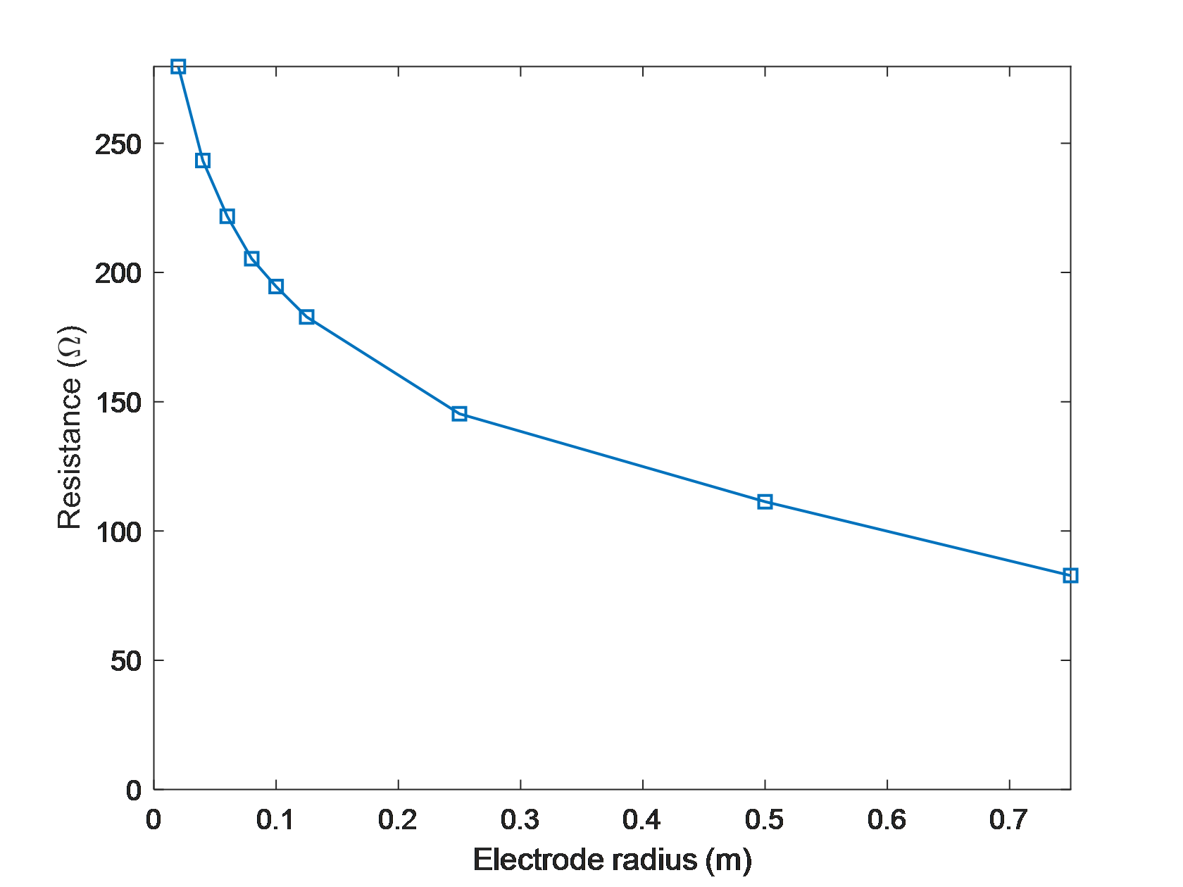
Figure 3 Earthing Resistance Variation According to the Electrode Length and Radius
The resistance of any earthing system mainly depends on the conductors characterisation, geometrical configuration of the system and the soil electrical parameters. This resistance is directly proportional to the soil resistivity as shown in Figure 4.
It is worth noting that the construction of earthing systems depends on the local codes applicable such as BS EN 62305 and IEEE Std 80. The purpose of these standards, however, is to establish a low-resistance (impedance in high frequency) path to the earth.
Soil resistivity is the key parameter that determines what the resistance of an earthing system will be, and to what depth the earth electrode must be driven to obtain low resistance. This parameter varies widely from one region to another in the world and changes seasonally. This variation should be considered when designing earthing installations. Indeed, the electrical resistivity of the soil is related to its content of electrolytes, which consist of moisture, minerals and dissolved salts. For instance, a dry soil has high resistivity if it contains no soluble salts. Table 1 demonstrates some types of soil and their electrical resistivity.
| Soil type | Electrical resistivity (Ω .m) | ||
| MIN | AVERAGE | MAX | |
| Ashes, cinders, brine, waste | 5.9 | 23.7 | 70 |
| Clay, shale, gumbo, loam | 3.4 | 40.6 | 163 |
| Soil with varying proportions of sand and | 10.2 | 158 | 1 350 |
| Gravel, sand, stones with little clay or loam | 590 | 950 | 4 580 |
Table 1 Electrical Resistivity Range of Different Type of Soil [5]
Soil resistivity must be carefully considered when designing earthing systems. Because of these different resistivities as shown in Table I, a change in earthing resistance or impedance will result. Furthermore, step and touch voltages can change accordingly towards higher values, leading to increased risk of lightning and fault currents.
According to IEEE std 81 [3], a proper selection of conductor material can maintain the integrity of an earthing system for years if the conductors are of adequate size and the soil conditions are not corrosive to the selected materials. The final choice of conductor material and dimensions should reflect numerous considerations related to each element of the earthing system, which should be able to maintain its function even when exposed to corrosion or physical abuse. In addition, the system should be reliable, and resists fusing and mechanical deterioration under the most adverse combination of a fault magnitude and duration.
Understanding how the resistivity can change is imperative for a safe design of earthing systems. The main aspects that give rise to differing soil resistivities are salt content, moisture content, temperature and permittivity. These factors together affect the resistivity of the soil as can be seen in the measured results in Figure 5, which describes the soil resistivity as a function of Wenner electrode spacings obtained at different dates.
![Soil Resistivity Measurements at Line R1 With Different Date [7]](https://kingsmillindustries.com/wp-content/uploads/2021/12/Soil-Resistivity-Measurements-at-Line-R1-With-Different-Date-7.png)
This variation in the soil resistivity affects the value of the earthing resistance. Figure 6 shows an example of the seasonal variation of earthing resistance of a vertical earth electrode for the period between Oct. 2010 and July 2011.
![Earthing Resistance Measurements at Different Date for Vertical Electrode (Reproduced from Reference [7])](https://kingsmillindustries.com/wp-content/uploads/2021/12/Earthing-Resistance-Measurements-at-Different-Date-for-Vertical-Electrode-Reproduced-from-Reference-7.png)
Temperature is an important factor to consider when designing an earthing system. It is directly related to soil resistivity and therefore must be examined to see how the two correlate to each other. Table III shows the resistivity of soil at varying temperatures. Sandy loam, containing 15.2% moisture, is considered where the temperature changes from 20° to -15°C.
| Temperature | Resistivity (⋅m) | |
| ֯ C | ֯ F | |
| 20 | 68 | 72 |
| 10 | 50 | 99 |
| 0 | 32 | 138 |
| 0 | 32 | 300 |
| -5 | 23 | 790 |
| -15 | 14 | 3,300 |
Table 2 Electrical Resistivity Variation With Temperature [5]
Due to seasonal variation, the natural moisture content of soil changes various times during a year. Since the moisture content in soil is an aspect that affects the resistivity greatly, it is therefore important to study its influence on the soil resistivity, thus, on the earthing resistance. In fact, several investigations (e.g., [1,2,5]) have concluded that soil resistivity greatly decreases as the moisture content increases. This is because the conduction in soil is electrolytic and transpires in pore spaces within the soil. An example is illustrated in Table II of two samples of soil.
Moisture content (%) by weight | Electrical resistivity (⋅m) | |
Top soil | Sandy loam | |
0 | >107 | >107 |
2.5 | 2,500 | 1,500 |
5 | 1,650 | 430 |
10 | 530 | 185 |
15 | 190 | 105 |
20 | 120 | 63 |
30 | 64 | 42 |
Table 3 Electrical Resistivity for Different Moisture Contents [5]
It is seen from these results that the resistivity of the soil rapidly decreases as the soil saturation degree increases and levels out at high saturation levels, until approximately 20% or greater moisture content is reached. In addition, the variation of the soil resistivity as a function of the moisture content depends on the soil nature, which means that each site should be studied independently.
Soil treatment by using low resistivity material provides a stable medium with good electrical conductivity and strength for the earthing system [3]. With Kingsmill Marconite, there are no seasonal variations in the earthing resistance, because Marconite does not rely upon water to conduct and does not shrink, unlike say, Bentonite. These materials are generally non-corrosive to steel or copper, which are the most commonly used material in earthing systems. They have a pH within the neutral range and do not attack cement structures.
Kingsmill Industries offers a variety of earthing products including earth bars, make sure to check them out on out website case you’re looking to install an earthing system.
For any further questions, please don’t hesitate to reach out to us at [email protected]. Or contact us through our website to submit a query.
[1] IEEE Std 367:2012, IEEE Recommended Practice for Determining the Electric Power Station Ground Potential Rise and Induced Voltage from a Power Fault.
[2] Vijayaraghavan et al., Practical Grounding, Bonding, Shielding and Surge Protection, Newnes, 2004.
[3] IEEE Std 80:2013, IEEE Guide for Safety in AC Substation Grounding.
[4] IEEE Std 81:2012, IEEE Guide for measuring earth resistivity, ground impedance, and earth surface potentials of a ground system.
[5] Workbook Edition 7.0, Understanding Ground Resistance Testing, 950.WKBK-GROUND 08/00, AEMC, 2018.
[6] Cavka et al., A Comparison of Frequency-Dependent Soil Models: Application to the Analysis of Grounding Systems, IEEE TEMC, vol. 56, no. 1, Feb. 2014.
[7] S. Mousa, “experimental investigation of enhanced earth electrode systems under high frequency and transient conditions”, PhD Thesis, Cardiff University, 2014.