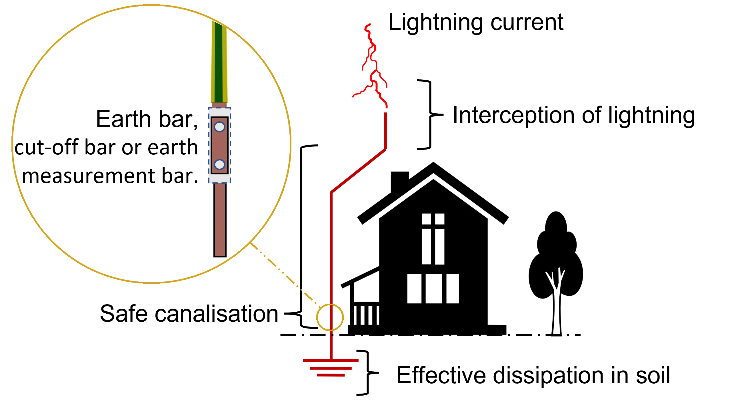
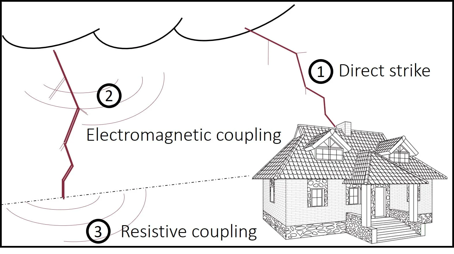
A requirement is to ensure that buildings are provided with lightning and surge protection systems in accordance with national and international standards. There are a large number of ways in which lightning and surges can interact with electronic equipment. These mainly include a direct strike, electromagnetic coupling, or through an induced potential caused by resistive coupling as illustrated in Fig. 1. Combinations of these coupling mechanisms may occur simultaneously in practical situations.
Complete protection is obtained when the entire building is enclosed in an electrically conducting box (Faraday cage), unwanted and fault currents flowing around the outside of the box will not generate any potentials inside [1]. Electronic equipment inside such a box will survive even a direct strike. In an ideal protection system, all equipment and metal parts inside the building are electrically connected together by the same conductor. This equipotential conductor is, situated at the level of the earth and connected to the earth termination systems by driven rods, or another appropriate combination of earth electrodes.
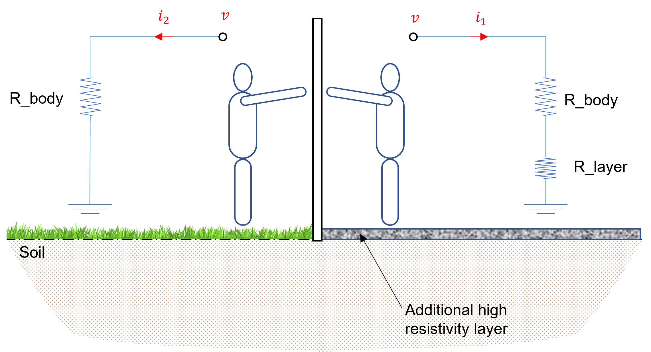
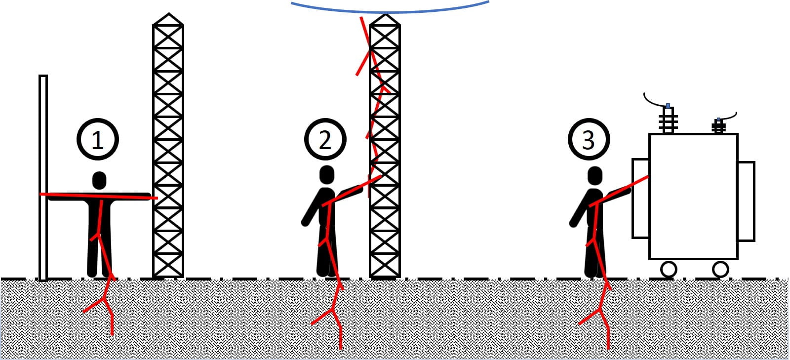
In the event of a fault in the electrical installation, one may receive an electric shock if an active metal part is touched as shown in Fig. 2. This is because in the absence of earthing system, electricity can use the human body as a path between the active part and the earth part [2].
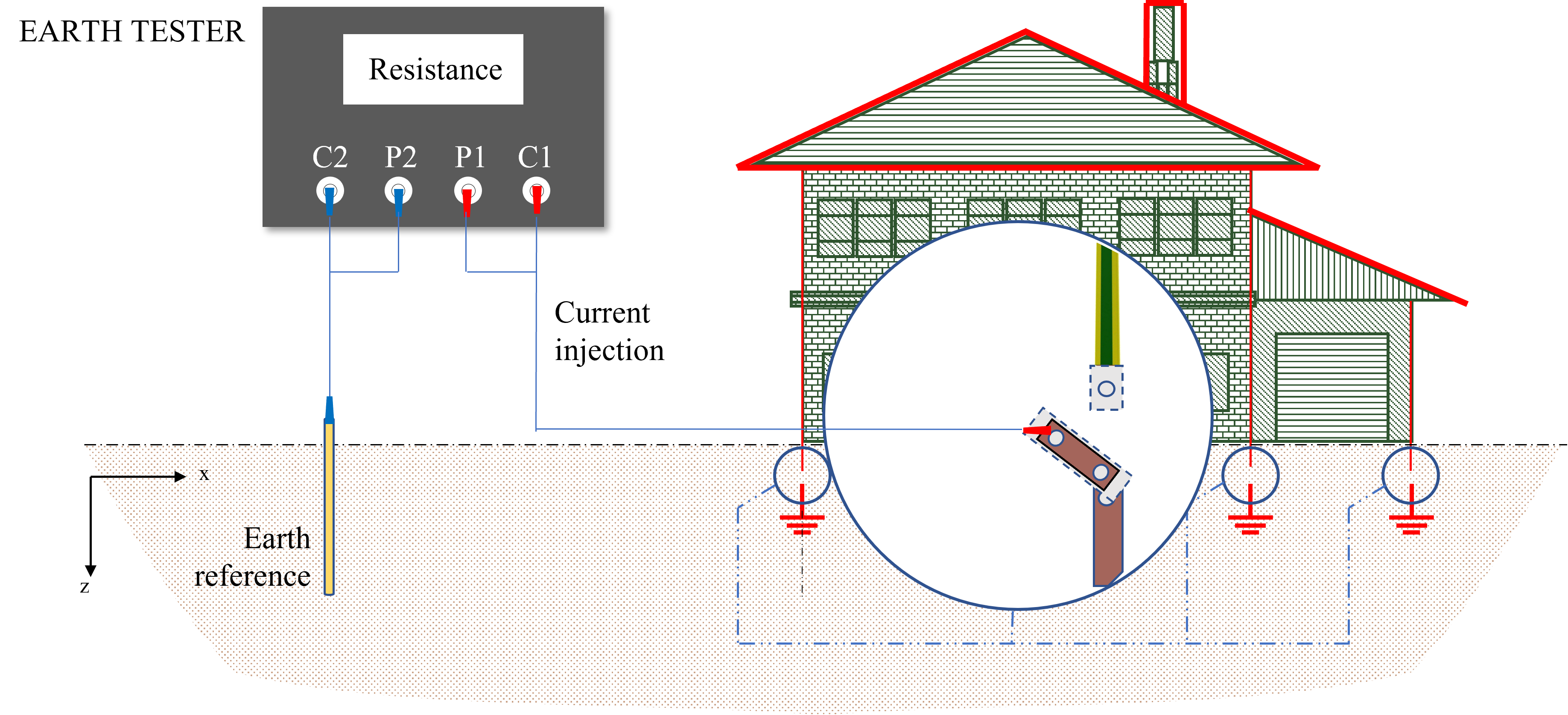
Measuring the earth resistance is very important to ensure the correct operation of the protection system. This resistance should be equal to, or less than, the tolerable value that is required for a given structure. Even though there are many methods for measuring the earth, pre-computation should be carried out to estimate the value of the earthing resistance.
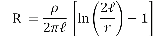
An earthing system should establish a path of low resistance/impedance towards the earth. This resistance/impedance depends upon the geometric configuration of the system itself and the surrounding environment. At low frequency range, many expressions have been developed for evaluating the earthing resistance of cylindrical vertical electrodes. These expressions mainly include those of Rudenberg, Dwight-Sunde and that of Liew-Darveniza [5].Dwight-Sunde
Liew-Darveniza
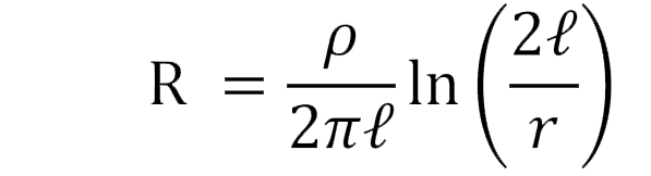
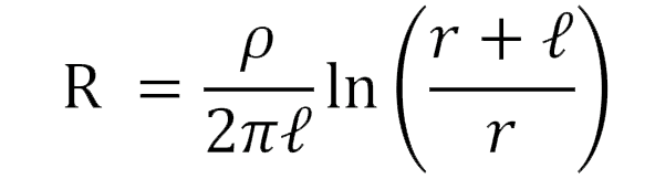
(1)
(2)
(3)
Where, l is the electrode length, r is the electrode radius and ρ is the soil resistivity.
Evaluating the resistance over the electrode length allows us to deduce that the expressions, although different, give very similar results for a given soil resistivity. The computed results are even closer than the length of the electrode is relatively large.
Obviously, the earthing resistance is directly proportional to the soil resistivity and inversely proportional to the electrode length. This is equivalent to saying that the soil resistivity and the rod length are the most important factors affecting the earthing resistance. In general, the longer the rod, the lower the earthing resistance. As you might suspect, driving a longer rod deeper into the earth, materially decreases its resistance. In general, doubling the rod length reduces resistance by about 40 percent.
The curve of Fig. 3 shows an overall indication of this effect, and how the earthing resistance is reduced as function of the electrode length. It can be seen that this technique is effective in shorter distances, and as the electrode increases in length, its effectiveness is limited.
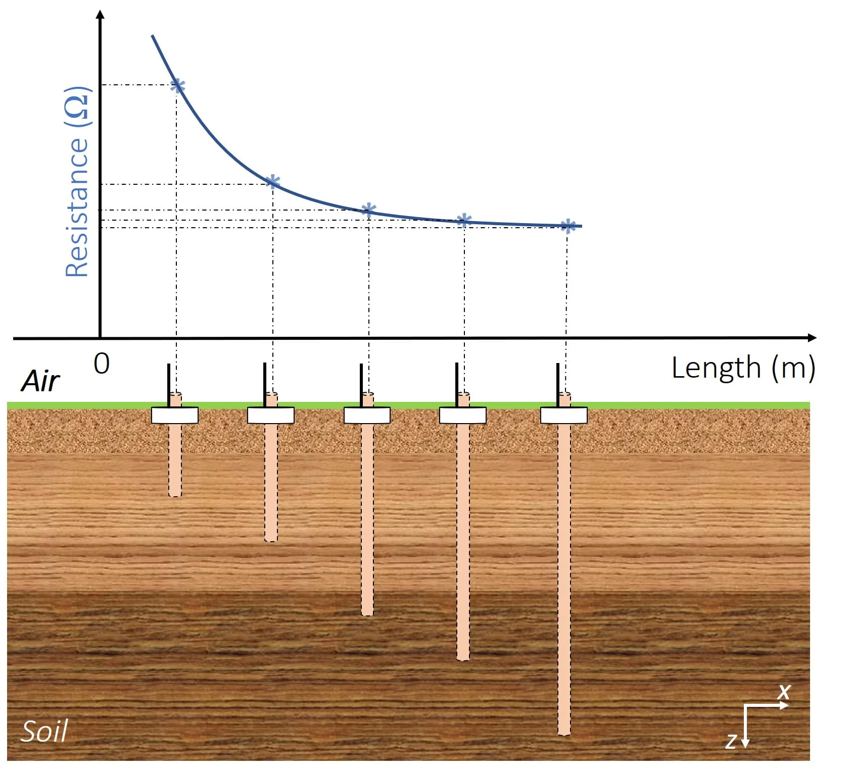
It is important to note that increasing the diameter of the earth rod does not have a significant effect on reducing the resistance of the earth system. Use of a larger diameter rod result poses extra installation considerations, since the rods will likely be buried both by hand and with pneumatic hammers.
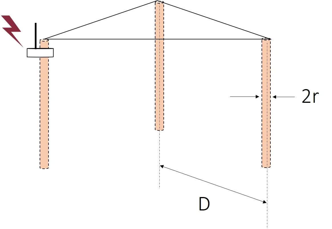
It is often impossible to achieve the desired reduction in soil resistance by increasing the length or radius of the earth electrode (physical reduction). Amongst the many techniques used to reduce the earthing resistance is the use of multiple earth electrodes. Several rods are then placed in the earth and connected in parallel to reduce earthing resistance. In most cases, the spacing distance between two rods should be at least equivalent to the depth of the installed earth electrode. Fig. 4 illustrates a graphic representation of the use of multiple earth electrodes, connected in parallel, in aligned manner. This figure also gives an indication to the reduction rate of the earthing resistance of the whole system as a function of the number of the connected earth rods.
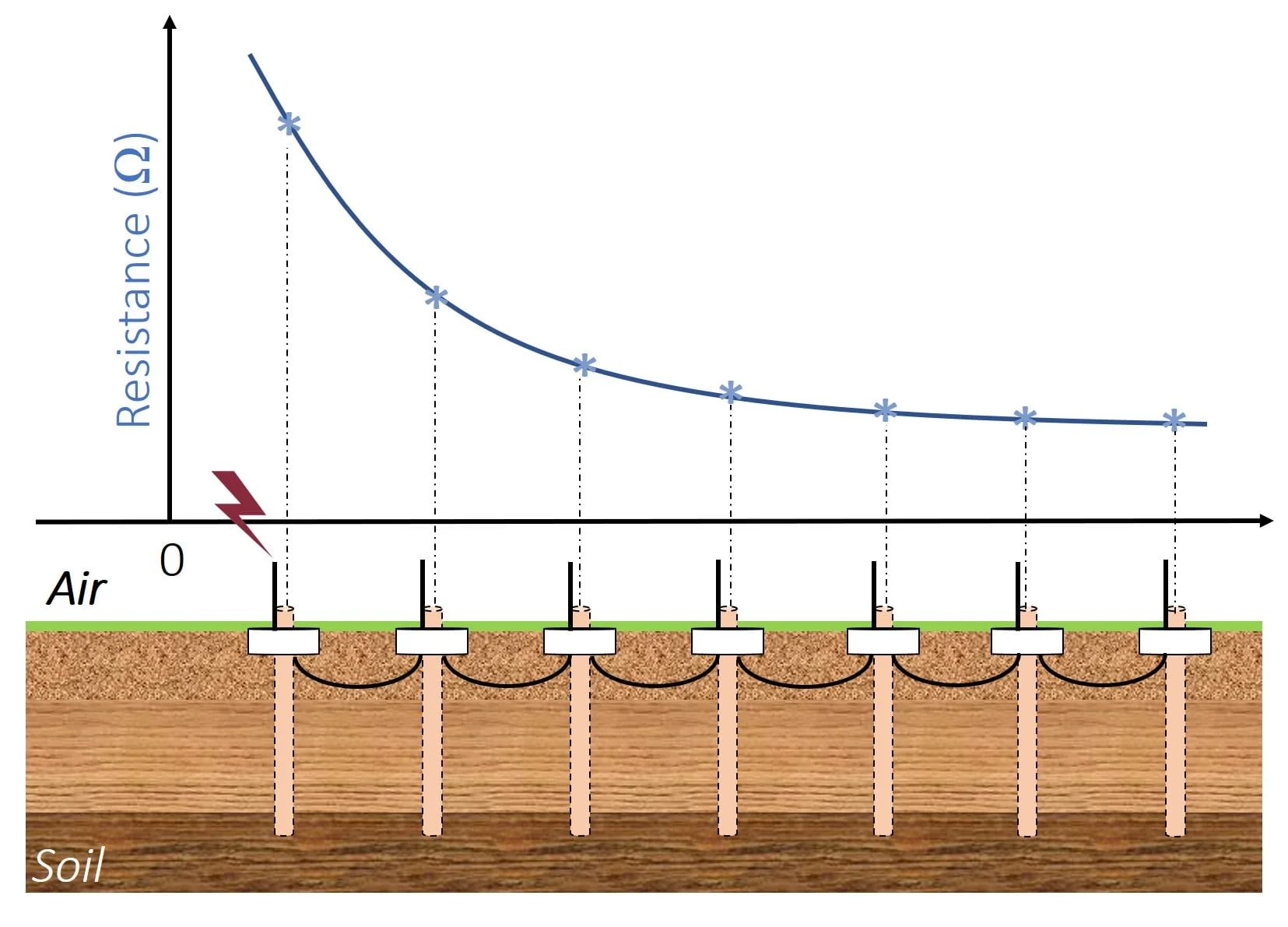
As can be seen from Fig. 4, attaching more rods gradually reduces the earthing resistance. In fact, the highest reduction in resistance occurs after installing the second and third rods. This reduction becomes smaller for a large number of additional rods.
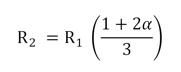
The equivalent resistance, R_2, of two identical electrodes in a straight line can be calculated by the following expression [6]:
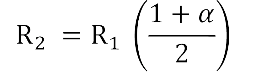
(4)
Where, R_1 and α are, respectively, the resistance of a single rod and a coefficient given by:
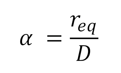
(5)
In which, D and r_eq are, respectively, the spacing distance between the electrodes and the equivalent radius [given by equation (6)] of the earthing rod to the hemisphere.
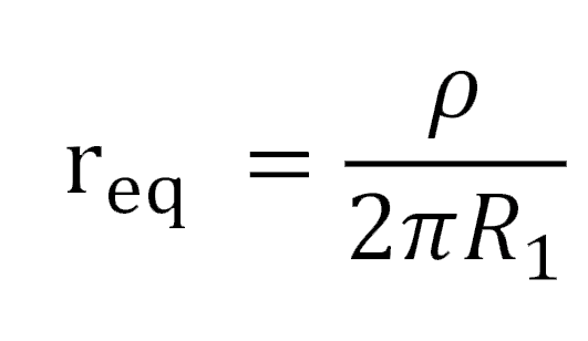
(6)
Moreover, the equivalent resistance of three identical electrodes in a straight line is given by:
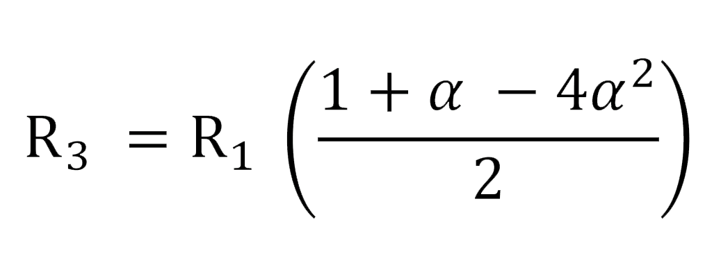
(7)
By generalizing the formula for n identical electrodes in a straight line separated from each other by the same distance D, the following approximate formula gives the resistance of the system [7]:
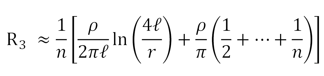
(8)
For the same configuration (n-electrodes) and arrangement of the n-electrodes, several other empirical expressions can be found in literature (e.g., [5 – 7]).
In the case of three identical electrodes placed at the vertices of an equilateral triangle (Fig. 5) of side D, the equivalent resistance is given by the following relation [6]:
(9)
In the literature, one can find many possible configurations and arrangements for an earthing system. As a general rule, the earthing resistance is reduced when the size of the system is increased. However, estimating this resistance remains difficult for these large-scale systems.
When the soil resistivity is high, and the resistance to ground exceeds the required values, specific techniques are useful to decrease it. This blog evaluates various methods for reducing the resistance of a earthing electrode based on the soil treatment techniques.
In some areas, it becomes impossible to obtain a low earth resistance by adding more network conductors or by paralleling the earth rods. It is theoretically known that an alternative solution to this problem is to effectively increase the diameter of the grounding electrode by modifying the soil surrounding the electrode [2].
Chemicals such as NaCl, MgSO4, CuSO4 or CaCl2 have been widely used, in areas with high soil resistivity, to increase the conductivity of the soil surrounding the electrode, thus, reducing the overall earthing resistance. The low resistivity results mainly from an electrolytic process between water and the additional salts [2].
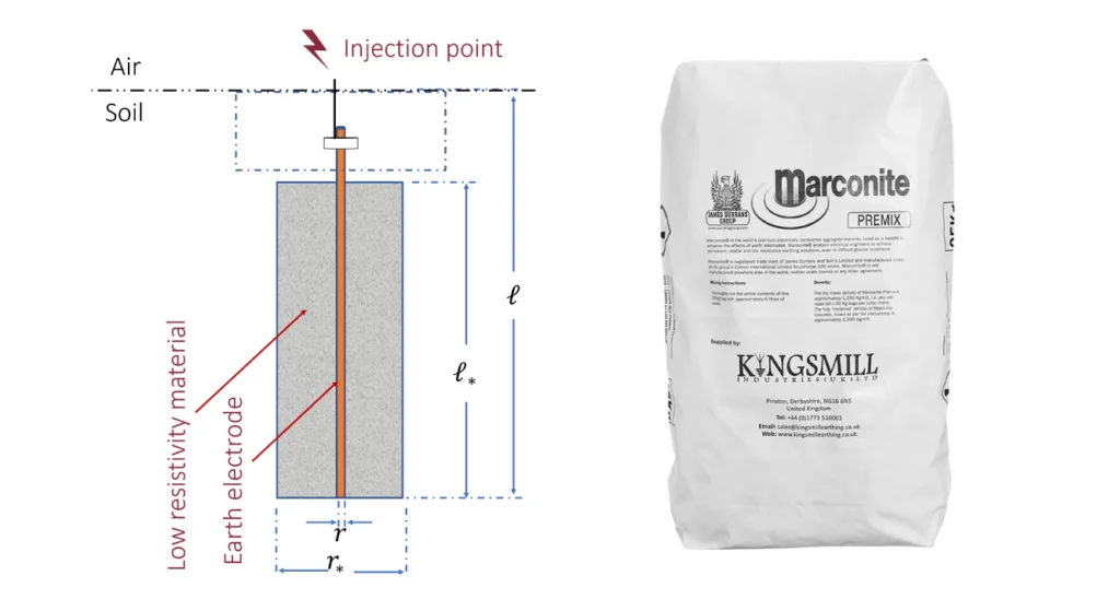
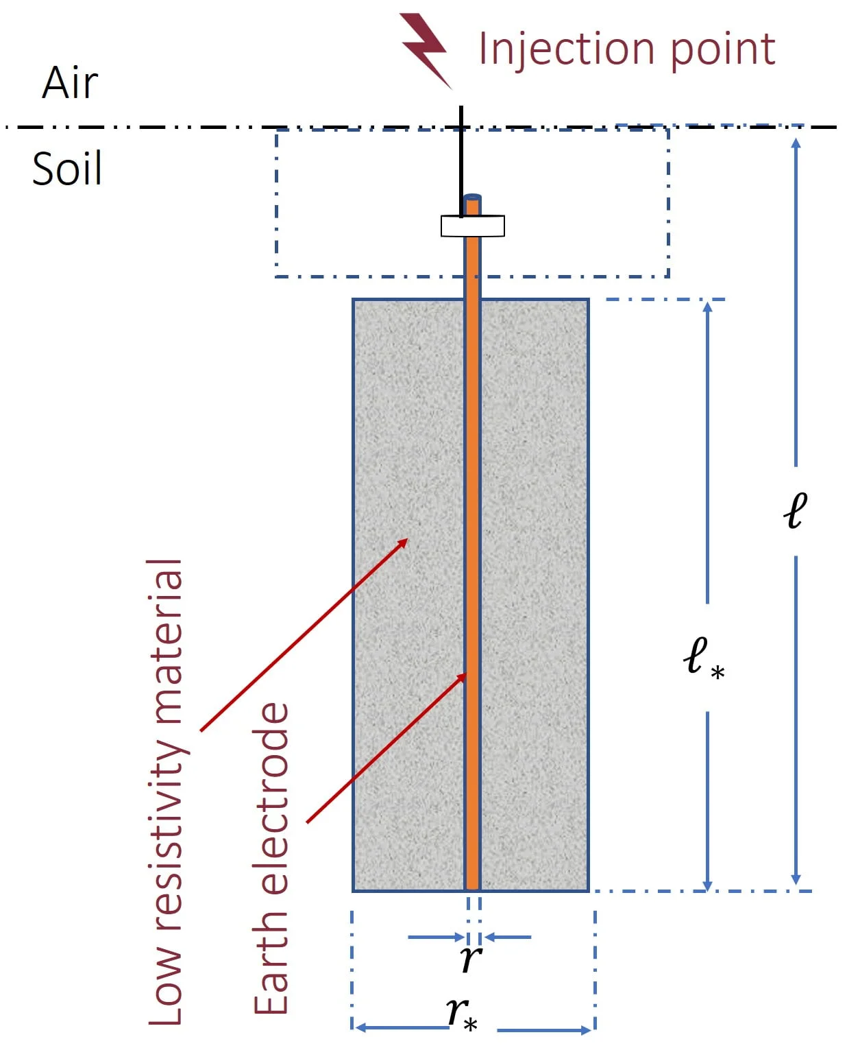
However, the result of adding some chemical (e.g., NaCl) causes a reaction between the copper electrodes and the salt itself, which in turn causes an ionisation process. For these circumstances, servicing and maintenance must be regularly adhered to since corrosion can result of the earthing electrode. Soil treatment by using low resistivity material (Fig. 6) provides a permanent medium with good electrical conductivity and strength for the earthing system [2]. Natural material and artificially adding chemicals into the earth have been proven to reduce the value of the resistivity of soil by up to 90%.
[1] “IEEE Recommended Practice for Grounding of Industrial and Commercial Power Systems,” IEEE Std 142-2007
[2] “IEEE Guide for Safety in AC Substation Grounding,” in IEEE Std 80-2013
[3] BS EN 62305, Protection against lightning, Standard
[4] NF C17-100, Lightning protection of buildings, Standard
[5] A.C. Liew and M. Darveniza, “Dynamic model of impulse characteristics of concentrated earths,” Proceedings of the Institution of Electrical Engineers, vol. 121, no. 2, pp. 123–135, Feb. 1974.
[6] M. A. Laughton and D. J. Warne, Electrical Engineer’s Reference Book, vol. 6. Elsevier Science, 2003.
[7] B. Claude, “Principes de conception et de réalisation des mises à la terre,” EDF Centre des études et recherches, Jan. 1984.